46
Section IV – Pipeline Under Pressure
3.0 Continued
E. Open the tapping valve.
F. Measure from the face of the valve to the mark
made on the adapter. Record this as
Measurement “M” (Figure 4.51).
Thread Paste
Drilling Machine
Measurement “M”
G. Add Measurements “M” + “N.” The sum of
Measurements “M” + “N” should be the body tube
reading when the plug holder contacts the bottom
of the recess in the PIG-SIG V.
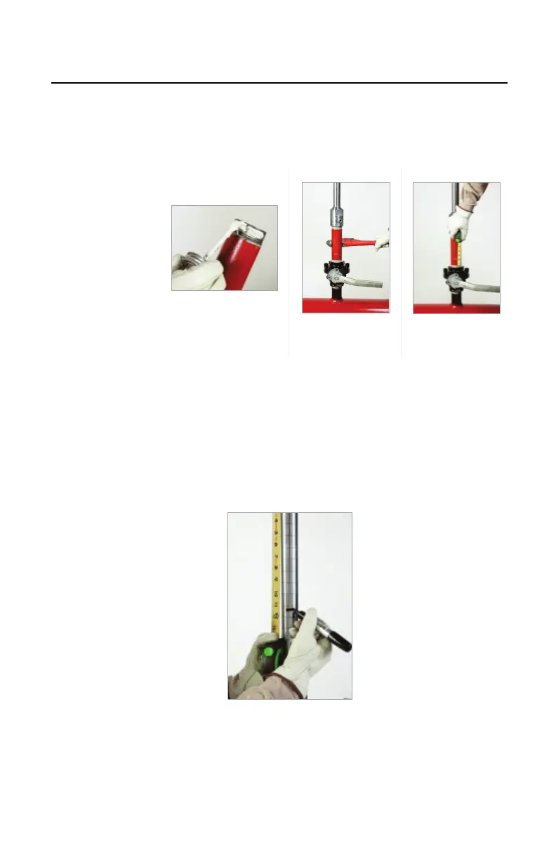
H. Measure from the bottom of the feed tube and
mark this measurement (the sum of “M” and “N”)
on the body tube (Figure 4.52).
Figure 4.52. Mark
Measurement.
See Measurement EXAMPLE on next page.
 Loading...