114-94052
REV. H1 20 of 31
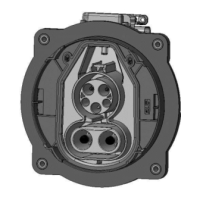
5.2.3 INSERT CONTACT PIN
Montage Kontaktpin
Insert contact pin until it stops against the contact of the cable assembly.
Kontaktpin bis zum Anschlag in den Kontakt der Leitungsassy eindruecken.
Figure 16: Insert contact pin
Abbildung 16: Kontaktbestueckung
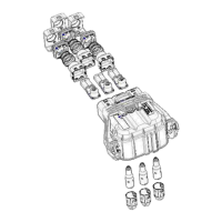
5.2.4 MOUNTING FINGER PROTECTION CAP
Montage der Fingerschutzkappe
Note the groove on the finger protection and the rib on the insulation part (only at pre-serial part). For
better understanding insulation part is shown in exploded assembling position.
Beachte die Nut in der Fingerschutzkappe und die Rippe an dem Isolationseinsatz (nur bei Vorserienteil).
Zum besseren Verstaendnis ist der Isolationstraeger im explodierten Zustand dargestellt.
Figure 17: Finger protection cap aligned to insulation part
Abbildung 17: Fingerschutzkappe zum Isolationskoerper ausrichten
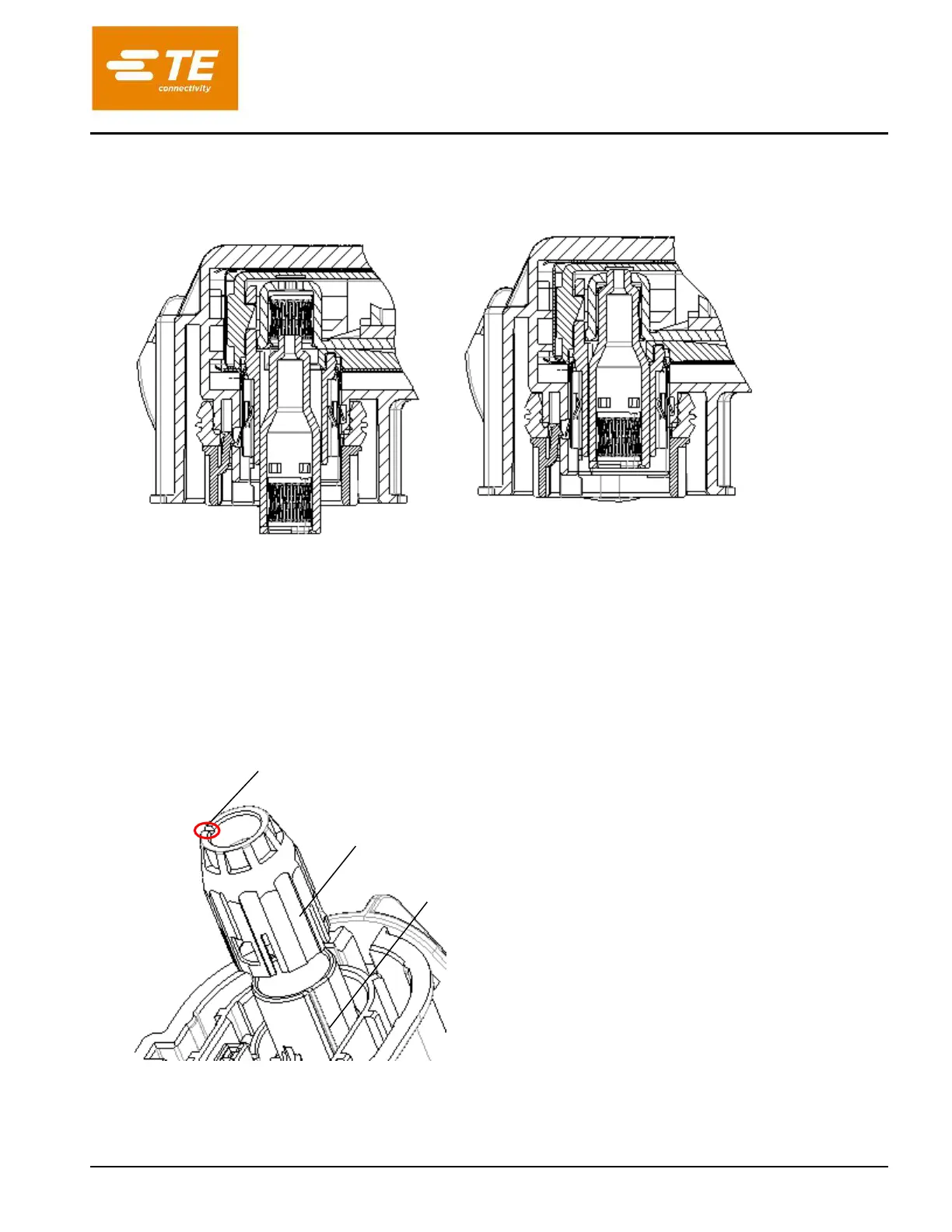
With the groove in the top (red marked, shown on fig. 18 too) and groove and rib inside (only at pre-serial
parts, see fig. 17 too) aligned, insert finger protection cap into the receptacle housing subassembly until it
Groove on inner side at pre-serial part (not shown in figure)
Nut in der Innenflaechebei Vorserienteil (in Abbildung nicht sichtbar)
Rib on outer side insulation part (at pre-serial part)
Rippe auf der Aussenseite des Isolationseinsatzes (bei
Vorserienteil)
Assembling aid through groove
Montagehilfe durch Nut
 Loading...