114-94052
REV. H1 3 of 31
7. LOCKING MECHANISMUS WITH LEVER AND CPA ..................................................... 22
VERRIEGELUNG MIT HEBEL UND CPA ................................................................................. 22
8. APPENDIX / ANHANG ..................................................................................................... 24
8.1 DATA SHEETS ............................................................................................................... 24
DATENBLAETTER ......................................................................................................... 24
8.1.1 COROPLAST – No. 9-2611 for wire range 16 – 50mm² ................................................. 24
DATENBLATT COROPLAST-NR. 9-2611 FUER LEITUNGSQUERSCHNITT 16 –
50MM² ........................................................................................................................................ 24
8.1.2 Leoni Silitherm wire size 35mm² ................................................................................. 27
Datenblatt Leoni Silitherm Leitungsquerschnitt 35mm² ............................................... 27
8.1.3 Leoni Silitherm wire size 25mm² ................................................................................. 28
Datenblatt Leoni Silitherm Leitungsquerschnitt 25mm² ............................................... 28
8.1.4 Cablena wire size 25mm² / Datenblatt Cablena Leitungsquerschnitt 25mm² .............. 29
8.1.5 Kromberg & Schubert wire size 35mm² ....................................................................... 30
Datenblatt kromberg & Schubert Leitungsquerschnitt 35mm² ..................................... 30
LIST OF FIGURES
Figure 1: HV Die holder ........................................................................................................ 12
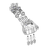
Figure 2: Exploded view Receptacle Housing assembly ....................................................... 12
Figure 3: Before processing slide components onto cabel sheath ........................................ 13
Figure 4: Cutting cable to length ........................................................................................... 14
Figure 5: Comb out screening braid ...................................................................................... 15
Figure 6: Contact crimp ......................................................................................................... 15
Figure 7: Prepare shielding parts for screening processing .................................................. 15
Figure 8: Processing screening braid .................................................................................... 15
Figure 9: Shield crimp ........................................................................................................... 16
Figure 10: Visual Examination of shield crimp ...................................................................... 16
Figure 11: Inspection dimensions of shield crimp ................................................................. 17
Figure 12: Mounting single wire seal on cover seal .............................................................. 18
Figure 13: Oriented cable assembly to housing .................................................................... 18
Figure 14: Insert cable assembly into the receptacle housing .............................................. 19
Figure 15: Assembly protection cover and single wire seal .................................................. 19
Figure 16: Insert contact pin.................................................................................................. 20
Figure 17: Finger protection cap aligned to insulation part ................................................... 20
Figure 18: Mounting finger protection cap ............................................................................. 21
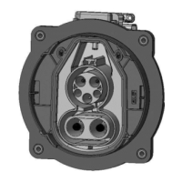
Figure 19: Visual Examination of assembled receptacle housing ......................................... 21
Figure 20: Delivery condition – CPA & lever closed .............................................................. 22
Figure 21: Release and actuate lever ................................................................................... 23
Figure 22: Plug position of lever ............................................................................................ 23