Do you have a question about the Teac W-470 and is the answer not in the manual?
Detailed technical parameters including tape speed, input/output levels, equalization, and head configuration.
Mechanical and electrical performance data, including speed deviation, wow/flutter, and frequency response.
Procedure for measuring and verifying tape playback wow and flutter performance.
Steps for adjusting and checking tape speed accuracy for both normal and high-speed modes.
Method for measuring and adjusting tape reel torque for proper tape handling.
Guidelines for lubricating mechanical parts, specifying appropriate oils.
Instructions for converting the unit's voltage setting for different regions.
Procedures for checking playback performance, including azimuth, output level, frequency response, and S/N ratio.
Tests for monitoring input levels, headphone output, and recording/playback performance.
Adjustments and checks for recording bias, level, frequency response, and signal-to-noise ratio.
Detailed checks of frequency response for playback, overall, and dubbing modes.
Visual breakdown of the unit's components with reference numbers for parts identification.
Second exploded view illustrating component placement and identification.
Third exploded view detailing various components and their assembly.
Diagram and parts list for the Jack PCB assembly.
Diagram and parts list for the Dolby Switch PCB assembly.
Diagram and parts list for the Timer Switch PCB assembly.
Diagram and parts list for the Meter PCB assembly.
Detailed diagram and parts list for the Main PCB.
Diagram and parts list for the Key PCB assembly.
Diagram and parts list for the Power PCB assembly.
Block diagram and pinout for the CX-20187 integrated circuit.
Block diagram and pinout for the NJM4558S operational amplifier.
Block diagram and pinout for the μ PC4570C integrated circuit.
Block diagram and pinout for the TC-4066BP analog switch IC.
Block diagram and pinout for the NJM7908FA voltage regulator.
Block diagram and pinout for the NJM7808FA voltage regulator.
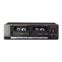
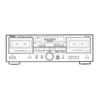
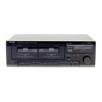
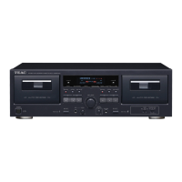
This document describes the TEAC W-470 Stereo Double Cassette Deck, a device designed for high-quality audio recording and playback using cassette tapes. The W-470 features a dual cassette mechanism, allowing for various functions such as continuous playback, high-speed dubbing, and simultaneous recording on two decks.
The TEAC W-470 is a stereo double cassette deck, meaning it incorporates two independent cassette mechanisms, typically labeled Deck I (Play I) and Deck II (Rec/Play II). This dual-deck configuration enables a range of functionalities beyond what a single deck can offer.
Playback: The device supports playback from both Deck I and Deck II. Deck I is primarily a playback-only deck, while Deck II is a record/playback deck. This allows for continuous playback from one tape to another, or for listening to a tape while preparing another for recording. The W-470 is designed to handle standard cassette tapes (C-60 and C-90 Philips type).
Recording: Recording is performed on Deck II. The W-470 supports recording from external sources connected via the LINE IN input. It also features a microphone input for direct voice or instrument recording. The device includes equalization settings for different tape types: METAL, CrO2, and NORMAL, ensuring optimal recording quality for each.
Dubbing (Tape-to-Tape Copying): One of the key features of a double cassette deck like the W-470 is its dubbing capability. Users can copy content from a tape in Deck I to a tape in Deck II. The W-470 offers a "Hi-speed Dubbing" function, which significantly reduces the time required to copy a tape, making it convenient for users who need to duplicate cassettes quickly.
Noise Reduction: The W-470 incorporates Dolby noise reduction technology. This feature is crucial for improving the signal-to-noise ratio of cassette recordings, reducing tape hiss and enhancing the overall audio clarity during both recording and playback. The "DOLBY" trademark and the double-D symbol indicate its licensed use of this technology.
Head Configuration: The device is equipped with specialized heads for optimal performance. Deck I features a playback head, while Deck II includes a 1/2-track, 1-channel erase head and a 1/4-track, 2-channel record/playback head. This configuration ensures efficient erasing before recording and accurate stereo recording and playback.
Motor System: The W-470 utilizes DC servo motors for both Deck I (playback) and Deck II (record/playback). Servo motors provide stable tape speed, which is critical for minimizing wow and flutter and ensuring consistent audio quality.
The W-470 is designed for user-friendly operation with a clear layout of controls and indicators.
Front Panel Controls: The front panel typically includes controls for basic cassette operations such as Play, Record, Fast Forward, Rewind, Stop, and Pause for both decks. There are also dedicated buttons for functions like "Hi-speed Dubbing" and "Dolby NR" activation. Input level controls (RECORDING LEVEL) and a balance control are provided for precise audio adjustment during recording. A headphone jack with its own output level control allows for private monitoring.
Input/Output Connections: The rear panel provides LINE IN and LINE OUT RCA connectors for connecting to other audio components like amplifiers, receivers, or other recording devices. This allows for seamless integration into a home audio system.
Tape Type Selection: The W-470 features an automatic tape selector. This means the deck can automatically detect the type of cassette tape (NORMAL, CrO2, or METAL) inserted, and adjust the equalization and bias settings accordingly for optimal recording and playback performance. This simplifies operation as users do not need to manually select the tape type.
Monitoring: The device includes a meter display to monitor audio levels during recording and playback, helping users prevent clipping and ensure proper signal strength. The headphone output allows for direct monitoring of the audio signal.
Timer Function: The W-470 includes a timer knob, suggesting compatibility with external timers for unattended recording or playback. This can be useful for recording radio programs or for waking up to music.
Operation Position: The device is designed for horizontal operation, ensuring proper functioning of its mechanical components.
Regular maintenance is essential to ensure the longevity and optimal performance of the W-470. The service manual provides detailed instructions for various adjustments and checks.
Cleaning and Demagnetization: Before performing any adjustments or checks, it is crucial to clean and demagnetize the entire tape path. This includes the heads, pinch rollers, and capstans, as residue buildup and magnetization can degrade audio quality.
Mechanical Adjustments:
Electrical Adjustments and Checks:
The W-470 is a comprehensive cassette deck designed for enthusiasts who appreciate the versatility of a dual-deck system, offering both advanced recording capabilities and convenient tape duplication features, all while emphasizing precise adjustments for optimal audio fidelity.
| Track System | 4-track, 2-channel stereo |
|---|---|
| Motor | DC servo motor |
| Frequency Response (Normal Tape) | 30 Hz - 14 kHz |
| Wow and Flutter | 0.08% WRMS |
| Output | 0.5 V (line out) |
| Outputs (Line Out) | 500mV (line) |
| Power Supply | AC 120V, 60Hz |