EasyManua.ls Logo

Teac Z-6000 Service Manual

Teac Z-6000
81 pages
To Next Page IconTo Next Page
Page #1 background imageLoading...
Page #1 background image
TEAC
SERVICE
MANUAL
26000
Master
Cassette
Deck
Effective:
May
,1983
8-30058
5704017200
Question and Answer IconNeed help?

Do you have a question about the Teac Z-6000 and is the answer not in the manual?

Teac Z-6000 Specifications

General IconGeneral
BrandTeac
ModelZ-6000
CategoryCassette Player
LanguageEnglish

Summary

SERVICE MANUAL

1 SPECIFICATIONS AND SERVICE DATA

Specifications

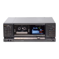
Technical details of the TEAC Z-6000 cassette deck.

Service Data

Technical specifications and data for service and maintenance.

CAUTION

2 REMOVAL OF EXTERNAL COMPONENTS

3 PARTS LOCATION

4 VOLTAGE ADJUSTMENTS AND CHECKS

VOLTAGE CONVERSION

Procedure for converting voltage for general export models.

DC VOLTAGE ADJUSTMENTS AND CHECKS

Adjusting and checking DC voltage levels at various test points.

5 MECHANICAL ADJUSTMENTS AND CHECKS

CASSETTE HOLDER ADJUSTMENT

Adjusting the clearance and closing mechanism of the cassette holder.

ADJUSTMENT OF CONTROL CAM POSITION

Adjusting the position of the control cam for proper tape path alignment.

PINCH ROLLER HEIGHT ADJUSTMENT

ERASE HEAD POSITION CHECK AND ADJ.

REC & PLAY HEAD ADJUSTMENT

PINCH ROLLER PRESSURE MEASUREMENT

REEL TORQUE ADJUSTMENT

TAPE RUNNING ALIGNMENT

TAPE SPEED ADJUSTMENT

WOW AND FLUTTER

DAMPER ADJUSTMENT

6-1 ADJUSTMENT POINTS

6 ELECTRICAL CHECKS AND ADJUSTMENTS

PRECAUTIONS

Important notes and precautions before performing checks and adjustments.

PLAYBACK PERFORMANCE

Performance checks and adjustments related to tape playback.

6-3 MONITOR PERFORMANCE

6-4 RECORDING PERFORMANCE

6-5 DBX PERFORMANCE

6-7 DBX PCB ADJUSTMENT

PREPARATION

Preparation steps before adjusting the DBX PCB assembly.

ENCODING ADJUSTMENT

Adjustments for the encoding section of the DBX PCB.

DECODING ADJUSTMENT

Adjustments for the decoding section of the DBX PCB.

6-6 MANUAL CALIBRATION

Internal OSC adj.

Adjusting the internal oscillator frequency.

METER calibration

Calibrating the meter levels.

EQ calibration range

Checking and adjusting the equalization calibration range.

BIAS calibration range

Checking and adjusting the bias calibration range.

LEVEL calibration range

Checking and adjusting the level calibration range.

7 EXPLODED VIEWS AND PARTS LIST

EXPLODED VIEW-1

Exploded view diagram showing the physical arrangement of components.

EXPLODED VIEW-2

EXPLODED VIEW-3

EXPLODED VIEW-4

EXPLODED VIEW-5

ASSEMBLING HARDWARE CODING LIST

8 PC BOARDS AND PARTS LIST

PLAYBACK AMPL PCB ASSY

Schematic diagram and parts list for the Playback Amplifier PCB.

REC AMPL PCB ASSY

Schematic diagram and parts list for the Record Amplifier PCB.

COUNTER PCB ASSY

Schematic diagram and parts list for the Counter PCB.

DOLBY PCB ASSY

DBX PCB ASSY

SYSTEM CONTROL PCB ASSY

AUTO STOP PCB ASSY

Schematic diagram and parts list for the Auto Stop PCB.

RESET PCB ASSY

Schematic diagram and parts list for the Reset PCB.

AMPL CONTROL PCB ASSY

Schematic diagram and parts list for the Amplifier Control PCB.

MIC AMPL PCB ASSY

MECHANISM PCB (1) ASSY

POWER SUPPLY PCB ASSY

TRANSISTOR PCB ASSY

CONTROL SW PCB ASSY

MANUAL BIAS PCB ASSY

PITCH CON PCB ASSY

HEADPHONE VR PCB ASSY

IN/OUTPUT PCB ASSY

SENSOR PCB ASSY

MECHANISM PCB (2) ASSY

MECHANISM PCB (3) ASSY

VOLUME PCB (1) ASSY

VOLUME PCB (2) ASSY

DIODE PCB (1) ASSY

DIODE PCB (2) ASSY

DIODE PCB (3) ASSY

CONDENSER PCB ASSY

POWER SW PCB ASSY (PC Board Omitted)

FUSE PCB(1) ASSY [E, UK, A] (PC Board Omitted)

FUSE PCB(2) ASSY [US, C] (PC Board Omitted)

SEMICONDUCTOR ELECTRODES

SYSTEM CONTROL IC TIMING CHART

TRANSPORT FUNCTION TABLE

Table showing transport functions and their states.

TEAC SCHEMATIC DIAGRAM Z-6000

POWER SUPPLY PCB Connections

Schematic connections for the Power Supply PCB.

MIC AMPL PCB Connections

Schematic connections for the Microphone Amplifier PCB.

PLAYBACK AMPL PCB Connections

Schematic connections for the Playback Amplifier PCB.

SYSTEM CONTROL PCB Connections

Schematic connections for the System Control PCB.

DBX PCB Connections

Schematic connections for the DBX PCB.

DOLBY PCB Connections

Schematic connections for the Dolby PCB.

AMPL CONTROL PCB Connections

Schematic connections for the Amplifier Control PCB.

COUNTER PCB Connections

Schematic connections for the Counter PCB.

MANUAL BIAS PCB Connections

Schematic connections for the Manual Bias PCB.

METER PCB Connections

Schematic connections for the Meter PCB.

REC AMPL PCB Connections

Schematic connections for the Record Amplifier PCB.

SW PCB (E) Connections

Schematic connections for SW PCB (E).

SW PCB (B) Connections

Schematic connections for SW PCB (B).

FUSE PCB Connections

Schematic connections for the Fuse PCB.

DIODE PCB (1) Connections

Schematic connections for Diode PCB (1).

DIODE PCB (2) Connections

Schematic connections for Diode PCB (2).

MECHANISM PCB (1) Connections

Schematic connections for Mechanism PCB (1).

HEADPHONE VR PCB Connections

Schematic connections for the Headphone VR PCB.

TEAC SCHEMATIC DIAGRAM Z-6000

DBX PCB Schematic

Detailed schematic diagram for the DBX PCB.

DOLBY PCB Schematic

Detailed schematic diagram for the Dolby PCB.

DECODER Schematic

Detailed schematic diagram for the Decoder section.

Related product manuals