25
Tester for Automotive Alternators BT030 Manual
EN
1. INTRODUCTION
The Tester for Automotive Alternators BT030 is
made of high-quality components and material through the
use of advanced techniques of diagnostic equipment ma-
nufacture.
The user manual contains information concerning
BT030 usage, equipment set, design, function, technical
characteristics and operation.
The manufacturer reserves the righ to change the
design and software of the equipment without prior notice
to users.
Read carefully user manual before putting BT030
(hereafter referred to as tester) into use. Take a special
training at the equipment manufacturing facility if neces-
sary.
1. APPLICATION
The equipment BT030 is designed to diagnose
automotive alternators with a supply voltage of 12V in two
ways:
• directly in the car;
• on the diagnostic test bench which provides its drive.
2. TECHNICAL CHARACTERISTICS
GENERAL
Dimensions (L*W*H), mm 120x65x18
Weight, kg 0,15
Supply voltage, V from 10 to 18
TFT-LCD Touch screen, color 2.8” screen size
Operating temperature, °C from 0 to +40
Storage temperature, °C from 0 tto +40
Ingress protection rating IP20
ALTERNATOR TESTING
Types of tested alternators <<COM>> (<<LIN>>, <<BSS>>),
<<SIG>>, <<RLO>>, <<RVC>>,
<<C KOR.>>, <<P-D>>, <<C
JAP>>
Tested parameters - Stabilizing voltage for COM
voltage regulators:
- ID;
- Protocol type
- Exchange rate
- Errors
Supply voltage of tested alternators, V 12
Polarity reversal protection Yes
Short-circuit sound alert No
Battery pack No
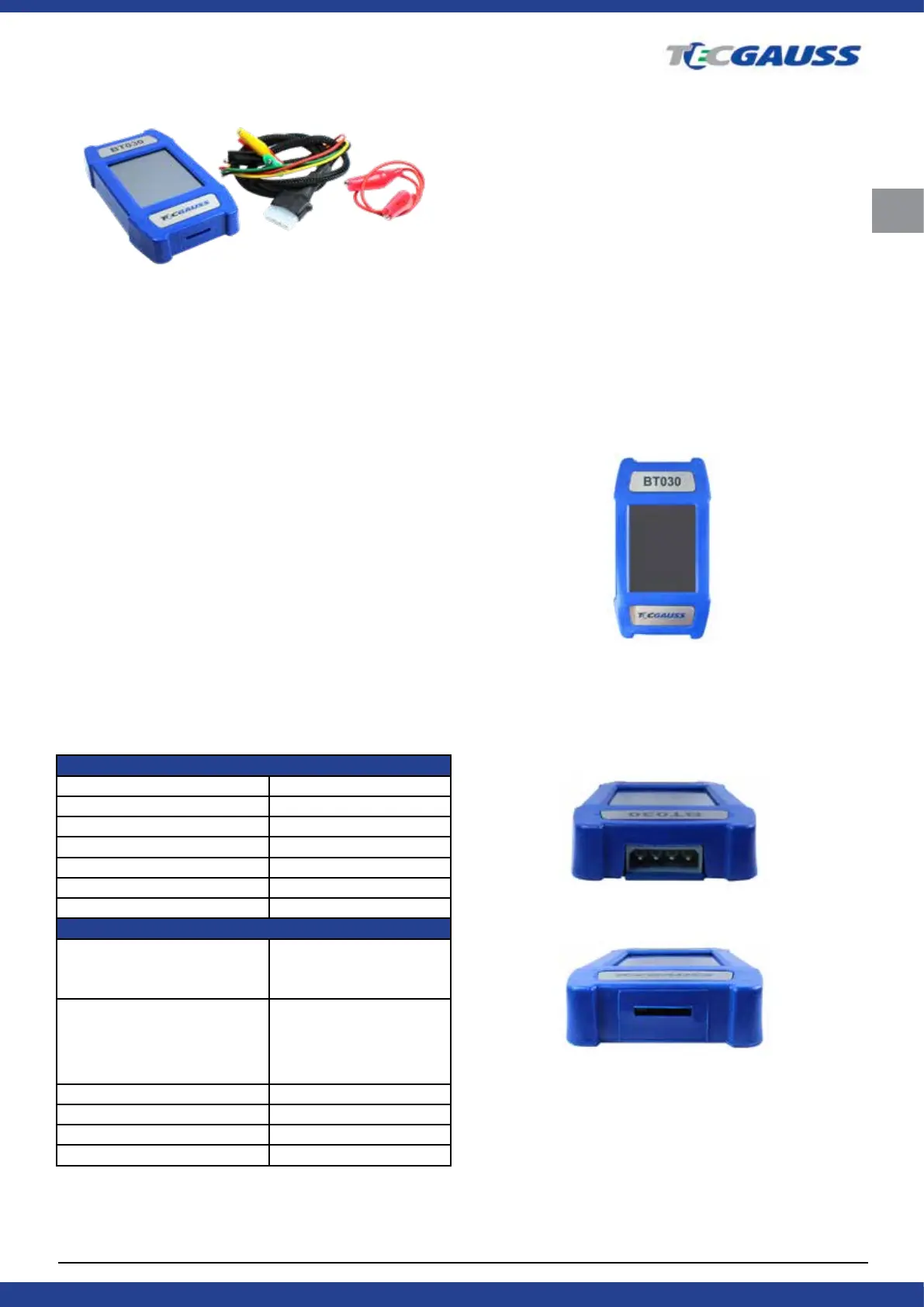
3. EQUIPMENT SET
The BT030 tester package includes:
Tester for Automotive Alternators GAUSS BT030 - 1 piece
Set of diagnostic cables:
Four-wire cable - 1 piece;
Cable for connection of additional "+" - 1 piece;
User manual - 1 piece.
Observe the Tester BT030 if any damage is detec-
ted, please contact the manufaturer or sales representati-
ve before launching the equipment.
WARNING! In case of obvious damage, the operation
of the equipment is forbidden.
4. DESCRIPTION
Fig. 1. Tester BT030. General view.
The tester is a compact device supplied with a
touch screen. A connector for diagnostic cable connection
is located in the upper part of the tester (Fig. 2), a MicroSD
connector for software updates - in its lower part (Fig. 3).
Fig. 2. Connector for diagnostic cable.
Fig. 3. MicroSD connector.
Two diagnostic cables are also included in the
equipment set (Fig. 4, 5): a diagnostic cable and an auxi-
liary cable to connect an additional positive contact.