30
Tester for Automotive Alternators BT030 Manual
EN
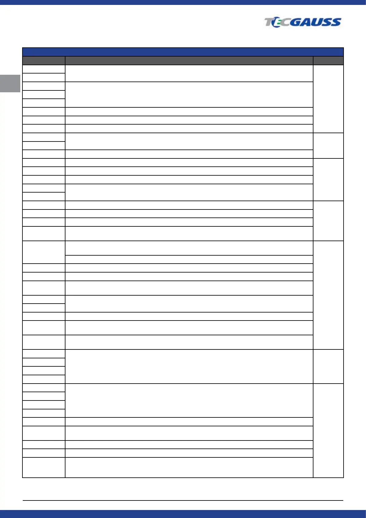
APPENDIX 1
TERMINALS FOR CONNECTION TO ALTERNATORS
Indicial notation Functional purpose Connection
B+
Battery (+)
B+
30
A
(Ignition) Input for switch startingIG
15
AS Alternator Sense
BVS Battery Voltage Sense
S (Sense) Input for voltage comparison at control point
B- Battery (-)
B-31
E Earth, Battery (-)
D+ Used for connection to an indicator lamp that transfers initial driving voltage, and indicates alternator operability
No
connection
I Indicator
IL Illumination
L (Lamp) Output for alternator operability indicator lamp
61
FR (Field Report) Output for load control on an alternator by engine management block
FR
DFM Digital Field Monitor
M Monitor
LI (Load Indicator) Same as FR, but with universal signal (Drive) Input of voltage regulator control with P-D termi-
nals Mitsubishi
D (Drive) Input of voltage regulator control with terminal P-D Mitsubishi (Mazda) and Hitachi (Kia Sephia 1997-
2000)
GC
(Digital) Input of code voltage installation on American Ford, same as SIG
RC (Regulator Control) same as SIG
SIG (Signal) Input of code voltage installation
RVC (L) (Regulated Voltage Control) Similar to SIG, but voltage change ranges from 11.0 V to 15.5 V. Control signal is
sent to L terminal
C (Communication) Voltage regulator input to control engine operation block. Japanese cars
G
RLO (Regulated Load Output) Input to control stabilizing voltage from 11.8 to 15 V (TOYOTA)
COM (Communication) General term for physical interface, alternator control and diagnostics. Protocols of use: BSD
(Bit Serial Device), BSS (Bit Synchronized Signal) or LIN (Local Interconnect Network)
LIN Direct indication on control interface and alternator diagnostics, condicted under LIN protocol (Local Intercon-
nect Network)
DF Output of voltage regulator
FR
F
FLD
67
P Output of one of alternator stator windings. used for measuring alternator driving voltage
No
connection
S
STA
Stator
W (Wave) Output of one of alternator stator windings for connection of tachometers in diesel engine cars
N (Null) Output of average stator winding point. Usually used to regulate alternator operability with mechanically
regulated voltage by an indicator lamp
D (Dummy) Blank, no connection, mostly in Japanese cars
N/C Not connected
Option of LRC
voltage
regulators
(Load Response Control) Function of voltage regulator response delay on. Load increase on an alternator.
Delay duration ranges from 2.5 to 15 seconds. On increasing the load (lights, cooler fan on), a voltage regulator
adds driving voltage smoothly ensuring stability of engine drive rotation. Remarkably seen under idle running
 Loading...