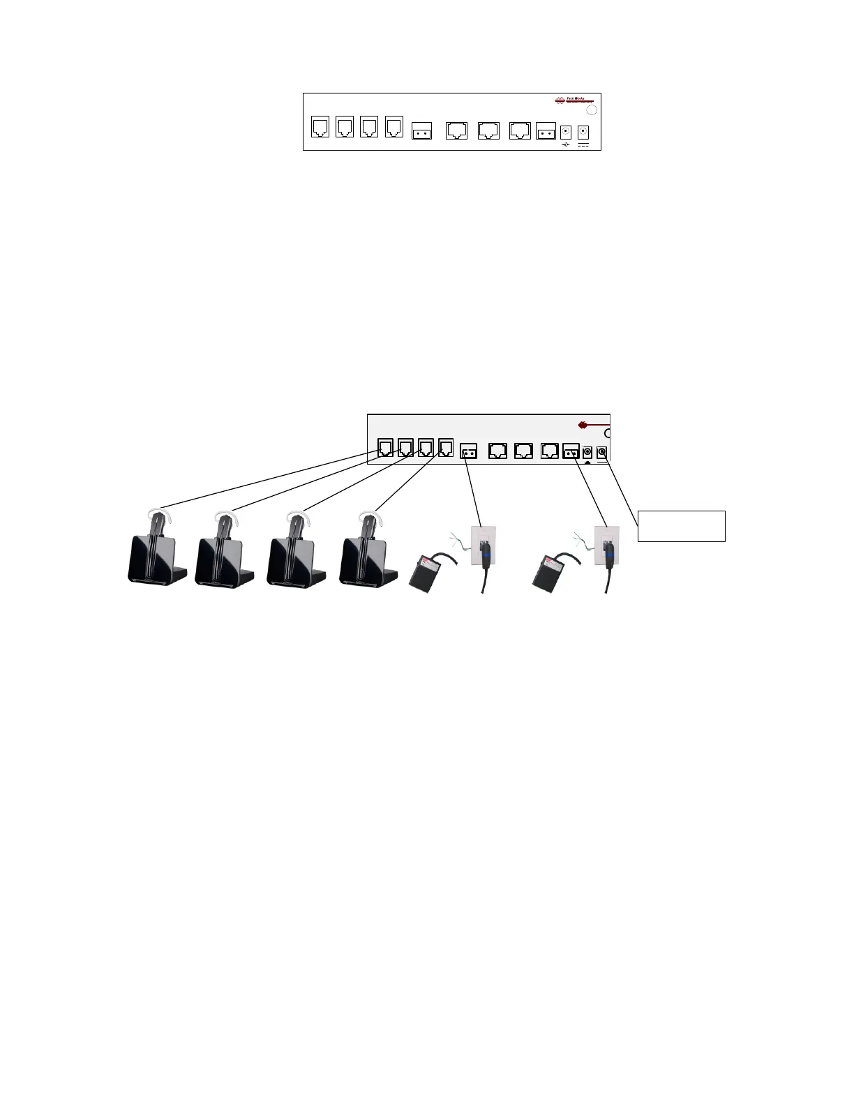
Headsets (Four): Connector: RJ-22, Telephone handset connectors
Talk Switch: Two Position Euro-Style Barrier Strip:
Switch Common
Talk Switch (+) (N.O.)
CI-BUSS, “Master” Connector, RJ-45,
CI-BUSS, “Slave” Connector, RJ-45,
PA-BUSS, "Monitor" Connector, RJ-45,
Call Switch: -Two Position Euro-Style Barrier Strip:
Call Switch (+), (N.O.)
Call Switch (-) Note: Call Switch must Float W.R.T. Common
Power Connectors: (Two) - 3.5mm Barrel Connectors
Chassis: Hex nut, Earth Ground
Note: The Chassis is connected to Circuit Common through a 1-Meg-Ohm resistor
Initial Adjustments:
To assure consistent performance each Headset requires initial adjustments. Please see the headset
data sheet for proper set up before connection or operation.
HSI-41 Microphone Gain Control: “9”
Microphone setup should be confirmed, when speaking at a normal level
The Setup Indicator on the HSI-41, should flash red
After all the microphones are set up, the Listening Levels may be adjusted by the user by adjusting
the listening level on the headset itself.
The “MONITOR LEVEL” Control sets the PA-BUSS output level.
Fully clock-wise is ~ 0dBM nominal output
There are several strategies for using this level setting:
1. Advance the control fully CW, and use the Amplifier Level Control
for setting Speaker Levels
2. Set the Amplifier Level Control Fully CW, and use the HSI-41 Level Control
to set Speaker Levels
3. If a system has several Amplifiers, the “Level” controls on the amplifiers may be used for
‘Balance’; the level control on the HSI-41 may be used as a ‘Master Level’ control