5 Technetix Group Limited Rev.1._0.1_0217
Chapter 2: RF amplifier
1357 99
16 10 17 18 191513 1412 11
68 4 2
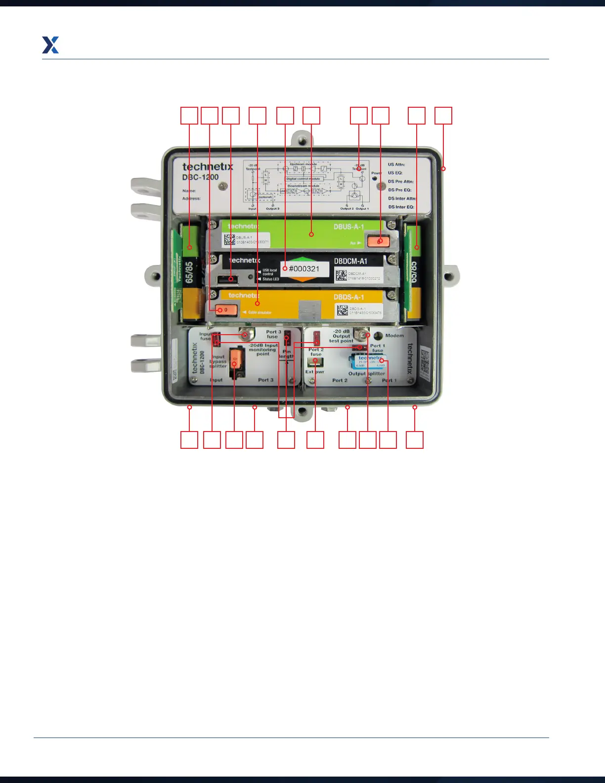
1. Removable power supply under cover plate
2. Optional local powering port (mains or 65 VAC)
3. Upstream amplifier module
4. Upstream auxiliary plug-in JXP attenuator location
5. Digital control module
6. Digital control module USB connection
7. Downstream amplifier module
8. Downstream cable simulator JXP location (can be
used for other types of JXP plug-in)
9. Input and output diplex filters.42/54, 65/85, 85/102,
85/105 and 204/258 options
10. Input bypass splitter location: 2-way splitter
PI-SPL-2W-12G; directional coupler tap 8dB
TX DC-8; tap 12 dB TX DC-12
11. Port power directors/fuses (micro2 automotive)
12. Input -20 dB test point (omnidirectional)
13. External bypass power for power continuity during
maintenance
14. Output downstream -20 dB test point (upstream
injection -20 dB test point)
15. Output splitter location: 2-way splitter
PI-SPL-2W-12G; directional coupler tap 8dB
TX DC-8; tap 12dB TX DC-12
16. Input RF port - PG11 thread with optional 5/8”
reducing ring for 5/8” threaded connectors
17. Port 3 RF output port- PG11 thread with optional 5/8”
reducing ring for 5/8” threaded connectors
18. Port 2 RF output port- PG11 thread with optional 5/8”
reducing ring for 5/8” threaded connectors
19. Port 1 RF output port- PG11 thread with optional 5/8”
reducing ring for 5/8” threaded connectors