Do you have a question about the technetix DBC-1200 and is the answer not in the manual?
Caution about AC voltages and adherence to notes and cautions in the user guide.
For network engineers and technicians planning, installing, and testing DBC-1200 amplifiers.
Lists tools and supplies for DBC-1200 installation, including connectors and software.
Details BLL software for Windows and BLA software for Android for DBC-1200 configuration.
Step-by-step guide to install BLA software on a phone/tablet, including enabling unknown sources.
Lists specific USB cable part numbers for connecting to the DBC-1200.
Lists available upstream (DBUS) and downstream (DBDS) modules with specifications.
Lists control (DBDCM), diplexer (DBDIP), and power (DBPSU) modules.
Overview of the DBC-1200's crossover design, RF function, and hybrid amplification stage.
Highlights advantages like digital control, GaN technology, energy efficiency, and surge protection.
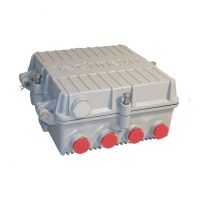
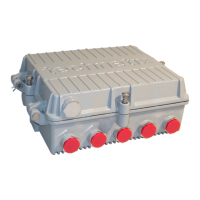
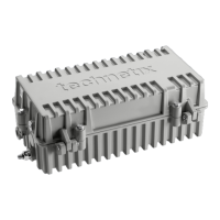
Labels and describes ports, modules, and features on the DBC-1200 amplifier's exterior.
Details the two methods for mounting the DBC-1200: side brackets or rear panel.
Step-by-step guide for attaching and using 'L' brackets for amplifier mounting.
Instructions for installing the fuse and checking amplifier and PSU LEDs after powering up.
Explains BLL software detection and setting amplifier type, diplexer type, and end frequency.
Details setting downstream inter-stage equaliser and attenuator values using BLL software.
Guides on setting pre-stage equaliser and attenuator for correct pilot tilt/slope and levels.
Adjusting pre-stage attenuator values to set pilot frequencies' levels and check tilt.
Explains setting Diplexer Type, Output IDS Control, and adjusting upstream tilt for signal levels.
Guides on adjusting attenuation for correct upstream levels, including single-person method.
Provides step-by-step instructions for replacing the Power Supply Unit (PSU) of the DBC-1200.
Continues PSU replacement: releasing connectors, removing PSU, and reverse installation.
Final PSU replacement steps: cover replacement, screw securing, and PSU LED check.
Details removing and installing downstream modules, including torque settings.
Describes removing and installing upstream modules, including torque settings.
Explains removing and installing digital control modules, including torque settings.
Covers general installation of the optical node, including fibre routing and powering.
Details connecting the downstream optical receiver and checking optical power levels.
Continues upgrade process: inserting fibre, connecting USB, configuring settings, and closing unit.
| Gain | 42 dB |
|---|---|
| Return Loss | 18 dB |
| Output Level | 121 dBμV |
| Noise Figure | 6 dB |
| Power Supply | 230 V AC |
| Operating Temperature | -20°C to +50°C |