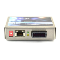
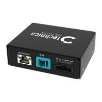
100/1000BASE-T1 MediaConverter MATEnetUser Manual
CONTENT
1 GENERAL INFORMATION ................................................................................. 4
1.1 Functionality and Features of the 100/1000BASE-T1 MediaConverter
MATEnet .......................................................................................................................... 4
1.1.1 Features .......................................................................................................... 4
1.1.2 General Information ....................................................................................... 5
1.1.3 LINKS .............................................................................................................. 5
1.1.4 General operating and safety strategy of Technica Engineering’s Products
5
1.1.5 General design rules for the power supply of Technica Engineering’s
products ....................................................................................................................... 6
1.2 Warranty and Safety Information ........................................................................ 6
1.3 RoHS Certificate of Compliance .......................................................................... 9
1.4 Scope of delivery .................................................................................................. 9
1.5 ChangeLog Hardware ........................................................................................... 9
2 HARDWARE INTERFACES ............................................................................... 10
2.1 Connectors .......................................................................................................... 10
2.1.1 RJ-45 Connector (1) .................................................................................... 10
2.1.2 MATEnet Connector (2) .............................................................................. 11
2.1.3 Power MQS Connector (3) .......................................................................... 12
2.1.4 Micro HDMI Debug Connector (4) .............................................................. 13
2.2 DIP Switches (5) ................................................................................................. 13
2.3 Status LEDs (6) ................................................................................................... 13
2.3.1 Resetting Error LED: ..................................................................................... 14
3 CONFIGURATION OF THE DEVICE .................................................................. 15
3.1 DIP switches........................................................................................................ 15
3.2 Configuration through Power MQS Connector ................................................ 16
3.2.1 Link Status Output (LS) (PIN 2) .................................................................. 16
3.2.2 Force Link Down (LD) (PIN 3) ..................................................................... 16
3.2.3 Force Slave mode (FS) (PIN 4) ................................................................... 16
3.3 Frame Generator ................................................................................................. 17

 Loading...