Do you have a question about the Technics RS-273US and is the answer not in the manual?
This document provides a comprehensive service manual for the Technics RS-273US and RS-273USD High-Fidelity Stereo Cassette Decks, offering detailed information for maintenance, adjustment, and parts replacement.
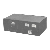
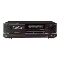
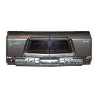
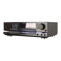
The Technics RS-273US/USD is a high-fidelity stereo cassette deck designed for recording and playback of audio on cassette tapes. It features a sophisticated mechanism for precise tape handling and includes advanced audio processing capabilities such as Dolby noise reduction. The deck is equipped with VU meters and a peak-level check switch for accurate monitoring of recording and playback levels. It also includes various controls for tape movement, recording level adjustment, and input/output selection, making it a versatile component for any stereo system.
The device operates on AC power, with different voltage and frequency specifications depending on the region:
The RS-273US/USD cassette deck is designed for user-friendly operation with a clear layout of controls and indicators.
The manual provides detailed instructions for disassembly, measurement, and adjustment, ensuring the longevity and optimal performance of the cassette deck.
General Notes: Ensure heads, capstan, and pressure roller are clean. Maintain a room temperature of 20°±5°C (68°±9°F). Input selector set to LINE IN, output control to MAX, tape select switch to NORMAL, and Dolby NR switch to OUT for most adjustments.
Pressure of Pressure Roller: Measured using a tension gauge (Standard Value: 600±100 gr). Adjusted by bending the pressure roller spring.
Takeup Tension: Measured using a cassette torque meter (RP-8063) (Standard Value: 55±15 gr-cm). If out of standard, clean rotational parts of the mechanism.
Head Azimuth Adjustment: Performed in playback mode using a VTVM, oscilloscope, and azimuth test tape (C-AA 6.3kHz). Adjust record/playback head azimuth screw for maximum output level and minimal level difference between channels. Lock screw with lacquer after adjustment.
Erase Head Adjustment: Uses a tape path viewer (RT-8133) to adjust the screw (D) so that the tape does not curl or malform. Lock screw with lacquer after adjustment.
Tape Speed Accuracy: Measured using a digital electronic counter or frequency counter (RP-8067) and test tape (C-WAT 3,000Hz) (Standard Value: ±2%). Adjusted via the tape speed adjustment VR.
Wow and Flutter: Measured using a wow meter and test tape (C-WAT 3,000Hz) (Standard Value: 0.09% or better JIS WRMS).
Playback Frequency Response: Measured using a VTVM, oscilloscope, and test tape (C-FH) (Standard Value: 0.5V (-6dB)). Adjusted via VR3 (L-CH) and VR4 (R-CH).
Playback Gain: Measured using a VTVM, oscilloscope, and test tape (C-FH) (Standard Value: 0.5V (-6dB)). Adjusted via VR3 (L-CH) and VR4 (R-CH).
Playback S/N Ratio: Measured using a VTVM, oscilloscope, and empty cassette (Standard Value: Greater than 43dB).
Bias Leak: Measured using a VTVM and oscilloscope (Standard Value: Less than 0.5V). Adjusted via trap coils L3 (L-CH) and L4 (R-CH).
Bias Current: Measured using a VTVM and oscilloscope (Standard Value: 0.12±0.02mA). Adjusted via trimmer capacitors VC1-1 (L-CH) and VC1-2 (R-CH).
Erase Current: Measured using a VTVM, oscilloscope, and 1Ω resistor (Standard Value: 130±20mA).
Overall Gain: Measured using an AF oscillator, VTVM, ATT, oscilloscope, and reference blank tape (C-RA) (Standard Input Level: LINE IN -24±3dB, Adjustment Procedure: Shows CrO2 Normal). Adjusted via VR7 (L-CH), VR8 (R-CH), VR1101 (L-CH), and VR1102 (R-CH).
Recording Current: Measured using a VTVM and oscilloscope (Standard Value: 60µA for CrO2, 40µA±1dB for Normal).
Level Meter Adjustment: Needle position and zero adjustment, followed by standard level indication adjustment via VR701 (L-CH) and VR702 (R-CH) to indicate 0 VU.
Overall Distortion: Measured using a distortion meter, AF oscillator, ATT, oscilloscope, and reference blank tape (C-RA) (Standard Value: Less than 2.3%).
Overall Frequency Response: Measured using a VTVM, AF oscillator, ATT, oscilloscope, and reference blank tape (C-RA for Normal, C-RF for CrO2). Adjusted via bias current (VC1-1, VC1-2) and peaking coils L5 (L-CH), L6 (R-CH).
Dolby NR Circuit: Adjusted via VR401, VR402, VR403, and VR404 to ensure proper Dolby tracking.
The manual includes diagrams showing the location of various electrical components on the main PCB and other circuit boards, facilitating troubleshooting and replacement.
Detailed schematic diagrams for the RS-273US and RS-273USD models are provided, illustrating the internal circuitry and connections.
A comprehensive wiring diagram shows how different components and PCBs are interconnected within the unit.
Exploded diagrams illustrate the mechanical assembly of the cassette deck, aiding in reassembly after repairs.
A list and diagram of cabinet parts are included for reference and replacement.
A detailed list of all mechanical, electrical, and cabinet parts, including part numbers, descriptions, and quantities, is provided for easy ordering and replacement. This list also includes resistors, variable resistors, capacitors, combination parts, transistors, diodes, thermistors, transformers, coils, switches, jacks, and pilot lamps.
| Brand | Technics |
|---|---|
| Model | RS-273US |
| Category | Cassette Player |
| Language | English |