EasyManuals Logo

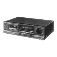
Technics RS-B465 Service Manual

Technics RS-B465
27 pages
To Next Page IconTo Next Page
To Previous Page IconTo Previous Page
Page #11 background imageLoading...
Page #11 background image
TERMINAL
FUNCTION
OF
IC
e
1C901
(M50940-263SP):
Microcomputer
Reference
Voltage
terminal
Mechanism
select
signal
(Not
used,
connected
to
GND)
Remote
control
select
(Not
used,
connected
to
GND)
Lch
level
display
Rch
level
display
Tie)
Division
iFTe)
Division
Bei
AC
POWER
off
detect
signai
Rec
enable
signal
(“L”:
rec,
“H”:
other)
|
|
GND
terminal
Reset
signal
(“L”:
reset)
OF
<
a
@
REF
1WAY/
REV
18.8
Dl);
oO
m||
>
ae)
on
mi
|<
al]
8
iw)
nN
N
>
8
CH
Clock
OSC
terminal
(4MHz)
Dire
i?)
<=
Not
used,
connected
to
GND)
Not
used,
open)
=~
6
KEY
2
KEY
1
x<
«|
X<
O!lo|
ZISi=
C
OUT
<
7)
W@W]
wl
o
NM]atlo
Key
SW
input
Reader
tape
det.
signal
LTD
System
clock
signal
(Not
used,
open)
a
wo
:
Zz
x
Reverse
rec
inhibit
Rotation
pulse
det.
signal
Line
out
mute
signal
(“H”:
ON,
“L”:
OFF)
REC
AMP
mute
signal
(“H”:
ON
“L”:
OFF)
BIAS
OSC
ON/OFF
control
(“H”:
ON
“L”:
OFF)
Rec
mode
signal
(“H”:
Rec
“L”:
other)
Dolby
NR
mode
select
signal
(“L”:
Dolby
C,
“H”:
other)
Forward
rec
inhibit
Mechanism
mode
SW
terminal
Cassette
half
det.
SW
teriminal
BY
=
4
Reference
voltage
terimal
(Negative
voltage)
<
no]
=)
=
4
10)
Brake
solenoid
hold
control
signal
Oo
at
On
a/W)/O
.e)
-
SOL
SOL
Brake
solenoid
trigger
control
signal
PLP
@O)
©
|
WO!]wW/]o!]w
=
oO,
SO
INIO!
a]
&
x=
>
rT
ia]
Trigger
solenoid
control
signal
Reel
motor
control
Cc
=
in
x
ra
(_
[stop
[Puay-FF|
REW
|
5
Dolby
NR
mode
select
signal
[RMA
|
ok
|
ok
|
Hw
(“L”:
Dolby
B,
“tH”:
other)
RMF
L
H
L
MPX
ON/OFF
control
signal
(“L”:
ON,
“H”:
OFF)
Capstan
motor
control
(“H":
ON,
“L”:
OFF)
16
44
Oo
ara
$
xD
0
=
Cue/rev
mode
control
is
(“H”:
cue/rev,
“L”:
other)
Q
By
fe)
I.
segment
control
signal
Ppa
fafalel
a.
Remote
control
signal
19
ARM
mute
rec
mute
Key
signal
56
1G
(“L”:
key
on,
“H”
key
off)
§
§
FL
grid
control
signal
62
7G
NC
Synchro
start
signal
(“L”:
start,
“H”:
stop)
Auto
tape
selector
signal
Nor
CrO,
Metal
ATSC
L
H H
ATSM
L L
H
AV
=
Power
supply
terminal
ve
(Positive
voltage)
Vv
+
Power
supply
terminal
oe
(Positive
voltage)
Timer
normal
or
abnormal
select
signal
(Normal:
“H”,
Abnormal:
“L”)
=
oO
4
Pe
BS
S|
po
Pl>
fép)
4
|
alal
g
zio
jl
M
INTERNAL
CONNECTION
OF
FL
¢
Grid
connection
diagram
6G
76
100
O00
Wag0g
p00
dopoo
M.stop
MPX
[B)
[C]
56
Rocoo
cone
soda
llontn
ontoo
oto
oot
pred
—_=15._="K
3
ko)
fa!
GUNN
WagO0”
WOON
|jOnwod
thood cngad
aoooD
=
C25
I/GrO2||I/Normal
W/Metal
4G
play
<>
¢
Anode
connection
table
en
ae
ee)
ee
ees
es
nnn
e
Pin
connection
eee
ae
bapa
aaa
FU)FIN|N
:
NIN|N|NIN|NIN|N|NININ
emma
evel
el
ele]
bfeielelsleleleieelels
Note
1.)
NPesvssesesseeses
Nopin.
Z)PL
PQ
Fi
rary
ar
wo
N
Cc
bs
N
C
loz
s|
=
12
=
M@
BLOCK
LINE
tN
(L
CH)
q
MIC
IN
(L
CH}
R/P
HEAD
(Leh)
ERA:
HEA

Questions and Answers:

Question and Answer IconNeed help?

Do you have a question about the Technics RS-B465 and is the answer not in the manual?

Technics RS-B465 Specifications

General IconGeneral
BrandTechnics
ModelRS-B465
CategoryCassette Player
LanguageEnglish

Related product manuals