,,
. . ..... . Record/Playback Head
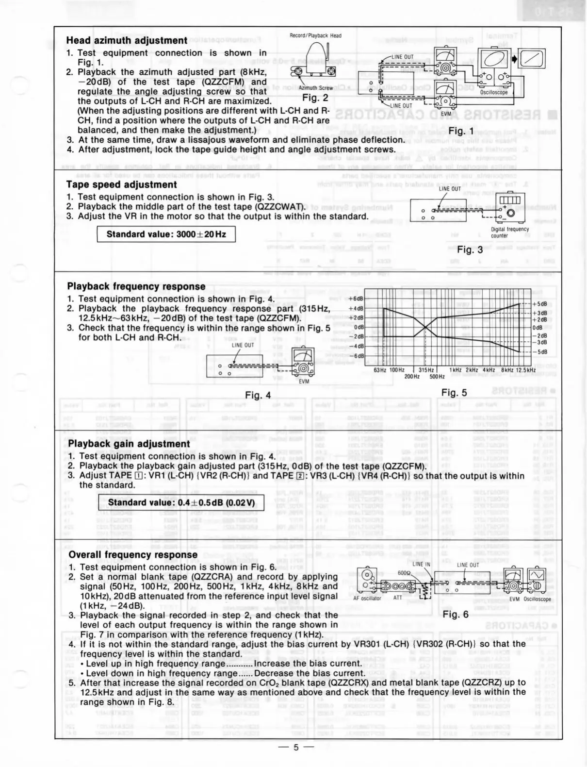
Head
azimuth adjustment
1.
Test equipment connection
is
shown
in
Fig.
1.
2.
Playback
the
azimuth adjusted part (8kHz,
-20dB)
of the
test tape (QZZCFM)
and
regulate
the
angle adjusting screw
so
that
^pT"
the outputs
of
L-CH and R-CH are
maximized.
"^'Q-
2
(When
the
adjusting positions
are
different with
L-CH and
R-
CH,
find
a
posltlon where
the
outputs
of
L-CH and R-CH are
balanced,
and
then make
the
adjustment.)
3.
At
the
same time, draw
a
lissajous waveform
and
eliminate phase deflection.
4.
After adjustment, look
the
tape guide height
and
angle adjustment screws.
EVM
Fig.
1
*9zyxwvutsrqponmlkjihgfedcbaZYXWVUTSRQPONMLKJIHGFEDCBA)ss
tnsMoanil
.SzyxwvutsrqponmlkjihgfedcbaZYXWVUTSRQPONMLKJIHGFEDCBA i
Tape speed adjustment mo-irtsnitr"ï8mbn6
ensq bisbn
1.
Test equipment connection
is
shown
in
Fig.
3.
i..
2.
Playback
the
middle part
of
the
test tape (QZZCWAT).
" -
•imuM
3. Adjust
the VR
In
the
motor
so
that
the
output
Is
within
the
Standard.
Standard value: 3000 ±20 Hz
1
\
LINE
OUT
j(i6m
'vil-
sfiT
.£
Digital trequency
»
counter
Fig.
3
Playback frequency response
i
1.
Test equipment connection
Is
shown
in
Fig.
4.
2.
Playback
the
playback frequency response part (315 Hz,
12.5kHz~63kHz, -20dB)
of
the
test tape (QZZCFM).
3. Check that
the
frequency
is
within
the
range shown
in
Fig.
5
for both
L-CH and R-CH.
. i i
.
• '
LINE
OUT
EVM
»UIEV
1
63Hz lOOHz ) 315Hz 1kHz 2kHz 4kHz 8kHz 12.5kHz
200 Hz 500 Hz
Fig.
5
Playback gain adjustment I joee
teemia»^
1.
Test equipment connection
is
shown
in
Fig.
4.
2.
Playback
the
playback gain adjusted part (315Hz, OdB)
of
the
test tape (QZZCFM).
3. Adjust TAPE
[3:
VR1 (L-CH) {VR2 (R-CH)}
and
TAPE
0:
VR3 (L-CH) (VR4 (R-CH)}
so
that
the
output
is
within
the Standard.
/«Ot
I j<"
Standard value: 0.4±0.5dB (0.02V)
.aosRi
LINE
IN
...
J\
CC
^
0
0 1
AF
oscillator
Fig.
6
Overall frequency response
' ^-^
o^,rxT<^'.o«^
1.
Test equipment connection
is
shown
in
Fig.
6.
2.
Set a
normal blank tape (QZZCRA)
and
record
by
applying
signal (50Hz, 100Hz, 200Hz, 500Hz,
1kHz,
4kHz, 8kHz
and
10kHz),
20dB attenuated from
the
reference input leve! signal
(1kHz, -24dB).
3. Playback
the
signal recorded
In
step
2,
and
check that
the
level
of
each output frequency
Is
within
the
range shown
In
Fig.
7 in
comparison with
the
reference frequency
(1
kHz).
4.
If It Is
not
within
the
Standard range, adjust
the
bias current
by
VR301 (L-CH) {VR302 (R-CH)}
so
that
the
frequency level
is
within
the
Standard.
• Level
up in
high frequency range Increase
the
bias current.
• Level down
In
high frequency range Decrease
the
bias current.
5. After that Increase
the
signal recorded
on
CrOj blank tape (QZZCRX)
and
metal blank tape (QZZCRZ)
up
to
12.5kHz
and
adjust
in
the
same
way
as
mentloned above
and
check that
the
frequency level
is
within
the
range shown
in
Fig.
8.
EVM
Oscilloscope
dotü
3öe.o
—
5 —
 Loading...