EasyManua.ls Logo

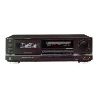
Technics RS-TR474

Technics RS-TR474
50 pages
To Next Page IconTo Next Page
To Previous Page IconTo Previous Page
Loading...
RS-TR474
|
Procedure
1-25-11
Sub
chassis
ee
~
eo
~
N
}
“Connector
holder
\
1.
Push
the.
drive.gear
in
the
direction
of
arrow@.
4.
Remove
the
sub
chassis
ass’y
in
the
direction
of
arrow@.
2.
Remove
the
4
screws(@~@Q).
5.
Remove
the
belt.
3.
Release
the
2
claws
in
the
direction
of
arrow@,
and
then
Note:
Care
must
be
taken
to
remove
the
sub
chassis
ass’y
remove
the
connector
holder
in
the
direction
of
arrow@.
with
tweezers
that
the
belt
is
not
applied
with
grease.
eRemove
the
2
screws(@,
@).
Mi
HOW
TO
CHECK
THE
MAIN
P.C.B.
1.
Remove
the
cabinet.
(See
Ref.
No.1
of
the
disassebly
instructions.)
2.
Remove
the
power
transformer.
(See
Ref.
No.3
of
the
disassebly
instructions.)
3.
Remove
the
rear
panel.
(See
Ref.
No.10
of
the
disassebly
instructions.)
4.
Remove
the
4
screws(@~@).
5.
Install
the
power
transformer
on
the
main
P.C.B.
and
power
supply
P.C.B.

Other manuals for Technics RS-TR474

Related product manuals