EasyManua.ls Logo

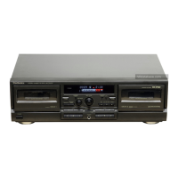
Technics RS-TR474

Technics RS-TR474
50 pages
To Next Page IconTo Next Page
To Previous Page IconTo Previous Page
Loading...
29
30
31
32
33
34
Ls
amc
(5)
Q709
2SC33IIAIRTA
LED
ORIVE
Q7TO7T
»
DTCILAESTP
oy
PEO
ORIVE
1c
702
XLU93LC46AFE
EEPROM
0701
LN2BRPX
(STANDBY)
For
(E,EB,
EG)
areas.
mMmonwp
(-8V)P;
(-5.6V)
Py
(+5.6ViP;
ic7ol
.
E.G)
rpt2
M38123M4101F
STD
RPS2
MICRO
COMPUTER
6)
Voo
(SYSTEM
CONT/
Ea)
FL
ORIVE)
wes
~4.8V
O.tys.
2V/DIV.
z7ol
RCOHC
-
278N
(SENSOR)
Ge-ranNnMooDgD
F=4MHz
R760
22K
R774
22K
(REC
LEVEL)
R720
VR702
1OOK(B)
15K
2SC33IIAIRTA
REC
BIAS
CONT.
WRT4S
MR746
KRTST
RR74E
R749
MR75SO
RTS
MR752
#R753
RR754
RRTS5
820
iK
1.2K
LSK
Lak
2.2K 3.3K
4.7K
6.8K
12K
2
8B
~
-
Ww Tt
o
-c
n
on
a
~
Ww
rE
ae
a
Ci
<
oo
oo
no
9
4
oD
wg
uy
Cnt
Cad
oF
oF
oF
93
ou
oz4
SEF
wel
wee.
ne
n4
nv
6K
8
re
n=
Ka]
no
sh]
KZe
an
»
ry
ak
“ny
az
we
os
ato
os
o>
ae
ES
ed
ea
ee
3
;
S
- 2
4
#R733
HR734
KR73S
MR7ZC
WR737
MR73B
HR739
KR740
RRTSI
ER742
HRT4S
820
'K
1.2K
t.5K 1.8K
2.2K 3.3K
4.7K
6.8K
12K
22K
START)
pss
RESET)
—_—
—_—
}—<o
s720
$723
(SYNCHRO
(4
OPEN/CLOSE)
$722
(REVERSE
MODE)
(SPEED)
$724
pi
at
fo
$7l2
(COUNTER2
Na
dD
CK
|
CIRCUIT
cN704
WRITE
CONNECTOR
L_@y
[tror
ic702)
ne
METER
Loh
|
ey
METER
Rch
(3)
+B
(E.VR)
me
E.VR
Leh
ea
{is}
0.GND
ol
+812)
(21)
+B
(3)
(29)
+
B14)
(3)
-VP
G4]
M.GND
G5)
HP
Rech
GHP
Loh
Ga
HP
GND
3
troRJmain
(14)
OMT
CIR
(CN3B)
UIT
JKTIO
HEADPHONES
|
RS-TR474
i
SCHEMATIC
DIAGRAM
(Parts
list
on
pages
57~60.)
(This
schematic
diagram
may
be
modified
at
any
time
with
the
development
of
new
technology.)
Note
1:
¢$701
:
Dolby
noise-reduction
switch
(DOLBY
NR;
Bl,
[€)).
¢S702
:
DECK
2
Stop
switch
(MM).
¢S703
:
DECK
2
Forward-side
playback
switch
(P).
¢S704
:
DECK
2
Reverse-side
playback
switch
(<d).
¢S705
:
DECK
2
Fast-forward
search
switch
(>
TPS).
¢S706
:
DECK
2
Rewind
search
switch
(<<q
TPS).
¢S707
:
DECK
2
Open/close
switch
(4
OPEN/CLOSE).
eS708
:
DECK
2
Record
switch
(@
REC).
¢S709
:
DECK
2
Pause
switch
PAUSE).
¢$710
:
DECK
2
Automatic-record-muting
switch
(Q
AUTO
REC
MUTE).
¢S712
:
DECK
2
Counter
reset
switch
(COUNTER
2
RESET).
¢©S714
:
Power
“STANDBY
«
/ON”
switch
(POWER,
STANDBY
©
/ON).
¢S715
:
DECK
1
Stop
switch
(MB).
¢S716
:
DECK
1
Fowarde-side
playback
switch
(p>).
°S717
:
DECK
1
Reverse-side
playback
switch
(<q).
°S718
:
DECK
1
Fast-forward
search
switch
(b>
TPS).
¢S719
:
DECK
1
Rewind
search
switch
(<<
TPS).
¢S720
:
DECK
1
Open/close
switch
(4
OPEN/CLOSE).
¢S721
:
Auto
tape
calibration
switch
(ATC).
¢$722
:
Reverse-mode
select
switch
(REVERSE
MODE).
¢
$723
:
Synchro-start
switch
(SYNCHRO
START).
¢S724
:
Tape-to-tape
recording-speed
switch
(SPEED;
X1,
X2).
eS725
:
DECK
1
Counter
reset
switch
(COUNTER
1
RESET)
¢S801
:
DECK
1
Cassette
holder
open
detection
switch
in
“off”
position.
°S802
:
DECK
1
Cassette
holder
close
detection
switch
in
“off”
position.
¢S$803
:
DECK
2
Cassette
holder
open
detection
switch
in
“off”
position.
¢S804
:
DECK
2
Cassette
holder
close
detection
switch
in
“off”
position.
eS971
:
DECK
1
Mode
switch
in
“off”
position.
¢
S971A
:
DECK
2
Mode
switch
in
“off”
position.
¢S972
:
DECK
1
Half
switch
in
“off”
position.
¢
$972A
:
DECK
2
Half
switch
in
“off”
position.
eS973
:
DECK
1
ATS
(CrO,)
switch
in
“off”
position.
¢
S973A
:
DECK
2
ATS
(CrO,)
switch
in
“off”
position.
¢S974A
:
DECK
2
Reverce
rec.
inhibit
switch
in
“off”
position.
¢S975A
:
DECK
2
Forward
rec.
Inhibit
switch
In
“off”
position.
¢
S976A
:
DECK
2
ATS
(Metal)
switch
in
“off”
position.
¢
Resistance
are
in
ohms
(Q),
1/4
watt
unless
specified
otherwise.
1K=1,000
(),
1M=1,000k
(Q)
¢
Capacity
are
in
micro-farads
(uF)
unless
specified
otherwise.
¢
All
voltage
values
shown
in
circuitry
are
under
no
signal
condition
and
playback
mode
with
volume
control
at
minimum
position
otherwise
specified.
(
)
scsueaces
Voltage
values
at
record
mode.
For
measurement
us
EVM.
¢
Important
safety
notice
Components
identified
by
A\
mark
have
special
characteristics
important
for
safety.
When
replacing
any
of
these
components,
use
only
manufacturer's
specified
parts.
(+B
>_—<)
indicates
+B
(bias).
°
(mim
mK
—B>w
mmm)
indicates
—B
(bias).
e(
sumone
)
indicates
the
flow
of
the
playback
signal.
o(
—>
)
indicates
the
flow
of
the
record
signal.
¢
The
supply
part
number
is
described
alone
in
the
replacement
parts
list,
>
marks
indicate
printed
resistor.
Caution!
IC
and
LSI
are
sensitive
to
static
electricity.
Secondary
trouble
can
be
prevented
by
taking
care
during
repair.
¢
Cover
the
parts
boxes
made
of
plastics
with
aluminum
foil.
¢
Ground
the
soldering
iron.
¢
Put
a
conductive
mat
on
the
work
table.
*
Do
not
touch
the
legs
of
IC
or
LSI
with
the
fingers
directly.

Other manuals for Technics RS-TR474

Related product manuals