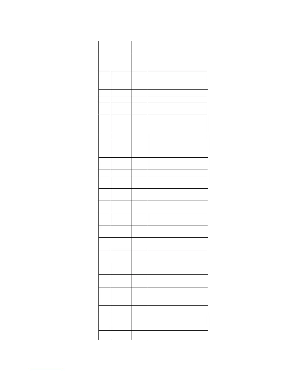
Pin
No.
Mark I/O
Division
Function
1 REG B — 3.3V external transistor
control terminal (Not used,
open)
2 REG M — 3.3V regular output
monitor terminal (Not used,
connected to GND)
3 NC — Not used, open
4 OPO O Op-amp output terminal
5 OP- O Op-amp invert output
terminal
6 OP+ O Op-amp non-invert output
terminal (Not used,
connected to GND)
7 Vcc I Power supply terminal
8 1/2
PVcc2
O 1/2 PVcc output terminal 1
(Connected to GND
through capacitor)
9 PVcc2 I Power supply terminal for
driver
10 PGND2 — GND terminal
11 VO4- O Tracking coil driver output
terminal
12 VO4+ O Tracking coil driver output
terminal
13 VO3- O Focus coil driver output
terminal
14 VO3+ O Focus coil driver output
terminal
15 VO2- O Traverse motor drive
output terminal
16 VO2+ O Traverse motor drive
output terminal
17 VO1- O Spindle motor drive output
terminal
18 VO+ O Spindle motor drive output
terminal
19 PGND — GND terminal
20 PVcc1 I Power supply terminal
21 1/2 PVcc O 1/2 PVcc output terminal 1
(Connected to GND
through capacitor)
22 VREF I Reference voltage input
23 IN1 I Spindle motor drive input
terminal
24 PC1 I Power cut 1 input terminal
25 IN2 I Traverse motor drive input