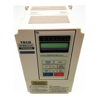
1-3
CAUTION
Location of equipment is important to achieve proper performance and normal operating
life. The 7200MA-model unit should be installed in area where the following conditions exist.
‧Ambient temperature : -10
o
C~+40
o
C
‧Install 7200MA in a location free from rain, moisture and not in direct sunlight.
‧Install 7200MA in a location free from harmful mist, gases, liquids, dusts and metallic powder.
‧Install 7200MA in a location without excessive oscillation and electromagnetic noise.
‧If more than 1 inverter are installed in a box, be sure to add a cooling fan or air conditioner to
maintain the air temperature below +40
o
C.
1.3 Removing/Attaching the Digital Operator and Front cover
Caution
Please disassemble Front Cover before you connect wires to terminals on 7200MA models.
‧220V 1~25HP & 440V 1~30HP models: Plastic instructions, so please disconnect LCD Digital
Operator before you disassemble Front Cover. After you finished the wiring connection,
assemble Front Cover first then reinstall LCD Digital Operator.
‧220V 30HP、40HP & 440V 40~75HP: Iron instructions, you can disassemble Front Cover for
wiring connection without disconnect LCD Digital Operator. Then reinstall Front Cover back
after you finished wiring connection.
7200MA disassembly / Assembly procedures will be depended on different model as
follows:
(A) For Compact Size Type 220V : 1-2HP, 440V : 1-2HP
■ Removing the digital operator :
Take off the two screws of the front cover in
the place a and b. Remove the front cover and
take off the screws in the place c and d.
Disconnect the RS-232 cable connector on the
back side of the LCD digital operator. And
then lift the digital operator upwards.
■ Mounting the front cover and digital operator :
Connect the RS-232 cable connector on the
back of the LCD digital operator.
LCD Digital
Operator
Front Cover
a
b
d
c
RS-232
Cable
Connector
Attach the digital operator and tighten the screws in the place c and d. Insert the tabs of
the upper part of front cover into the groove of the inverter and tighten the screws in
the place a and b.

 Loading...


