1-9
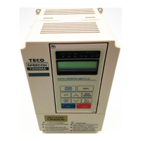
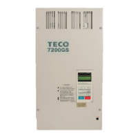
(B) 220V : 3-40HP, 440V : 3-75HP (NEMA4 to 20HP)
.JNTMBG
□□□□
JK
---
.JNTMBG
□□□□
AZ---
IP12
OPEN
PULL UP
B1/P B2
Braking Resisto
MCNFB
24VG
Shield Sheath
E
(Sink Common)
FW D/STOP
REV/STOP
External Fault
Multi-Step
Speed Ref.1
Jogging
cc. & Dec.
Switch
Factory Prese
V/T2
W/T3
IM
U/T1
Main Ck
Power Suppl
R/L1
S/L2
T/L3
Multi-Step
Speed Red.2
Fault RESET
GND Analog signal Common
+12V or -12 Power Suppl
for
Speed Ref.
(+12V or -12V, 20 mA)
IN Master Speed Ref.
VIN Master Speed Ref. 0V ~ 10V & -10V~10V
, (20kΩ)
UX Multi-Function
Analog Input
0 ~ 10V, (20k
)
2k
Ω
1/2W
P
P
P
-10V ~ +10V
4 ~ 20 m
0 ~ +10V
0V
4 ~ 20 mA, (250
)
EXTERNAL FREQUENC
COMMAND
24V
(Source Common)
O1
Grounding Lead
(<100
Ω
)
GND
O2
nalog
Output 1
nalog Monitor 1, 2
(DC 0 ~ 10 V)
nalog
Output 2
E
Multi-Function Contact Output
250V AC, <1A
30V DC, <1A
R1A
R1B
R1C
R2A
R2C
RS-485 Port
S(+)
S(-)
Multi-Function Output 1
Open Collector 48V, 50mA
DO1
DOG
FW D ("Close":FWD)
REV ("Close":REV)
Eb
RESET
Multi-Function
Contact Input
2
3
4
5
6
7
8
1
(*1)
*2
The terminal can be set as SINK or SOURCE t
e in
ut interface, when settin
as sink t
e
input, the short jumper of TP2 must be set to SINK position, and set to SOURCE position for source type input.
(*3) The terminal arrangement
(*4) The control board code No. : 4P101C0060002
P
Shield
Wire
Shielded
Twisted Wire
24VG
13 5 7
UXVIN
IN24V DO1 DOG IP12
(+)
(-)
E2
4 6 8 +12VGND
O1
O2 E IG12 S(+) S(-)GND R2A R2C R1A R1B R1C
1
8
~
1 8
~
(*1)
(+)
(-)
PG INPUT
(A PHASE)
IP12
IG12
EXTERNAL PG
DC VOLTAGE
(* 2)
TP2 :
TP2 :
SINK
SOURCE
TP1
Install fast action
fuse
Fig. 2-b Standard connection diagram
(*1)
The terminal
c
and
j
can be set
as SINK or
S OURCE
type input interface, when setting
c
~
j
as sink type input, the short jumper of TP2
must be set to SINK posit
ion, and set to SOURCE position for source type input.
P
Shield Wire
Shielde Twisted
Wire
The terminal arrangement
The control board code No.
:
4P101C0060002 (220V 3-20HP, 440V 3-20HP), 4H300D6740006 (220V 25HP, 440V 25-30HP),
4H300D6750001 (220V 30-40HP, 440V 40-75HP)
24VG
1 3 5
7 VIN AIN
AUX DO1
24V DOG
IP12
A(+)
A(
-)
E 2
4
6 8
+12V
-
12V
AO1 AO2 E
IG12
S(+)
S( - ) GND
R2A R2C R1A R1B R1C
For 220V 25-40HP, 440V 25-75HP inverters, VIN Ref. can be set in two input methods as 0~10V or -10~+10V
The terminal A(+), A(-) can be the output terminal of Pulse Input Frequency Command, and the jumper of TP1 must be set to OPEN position.
Pulse Input Frequency Command: 50Hz~32KHz, 3~12V High Voltage Level, input resistor 2.7KΩ
(*2)
(*3)
(*4)
(*5)
(*6)
Fig. 2-b Standard connection diagram

 Loading...


