Challenger10 Installation and Quick Programming Manual 11
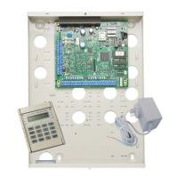
2. Insert the bracket with tamper switch into the 1 cm slot on top left-hand side
of the enclosure (Figure 4 on page 9, item 3).
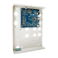
To mount the Challenger board to the enclosure:
1. Remove the Challenger board from its antistatic bag.
2. Use four M3 x 14 pan head screws to fix the Challenger board to the
enclosure’s standoffs (Figure 4 on page 9, item 2).
3. Slide the board’s terminal connectors together and mount them to the board.
Connections
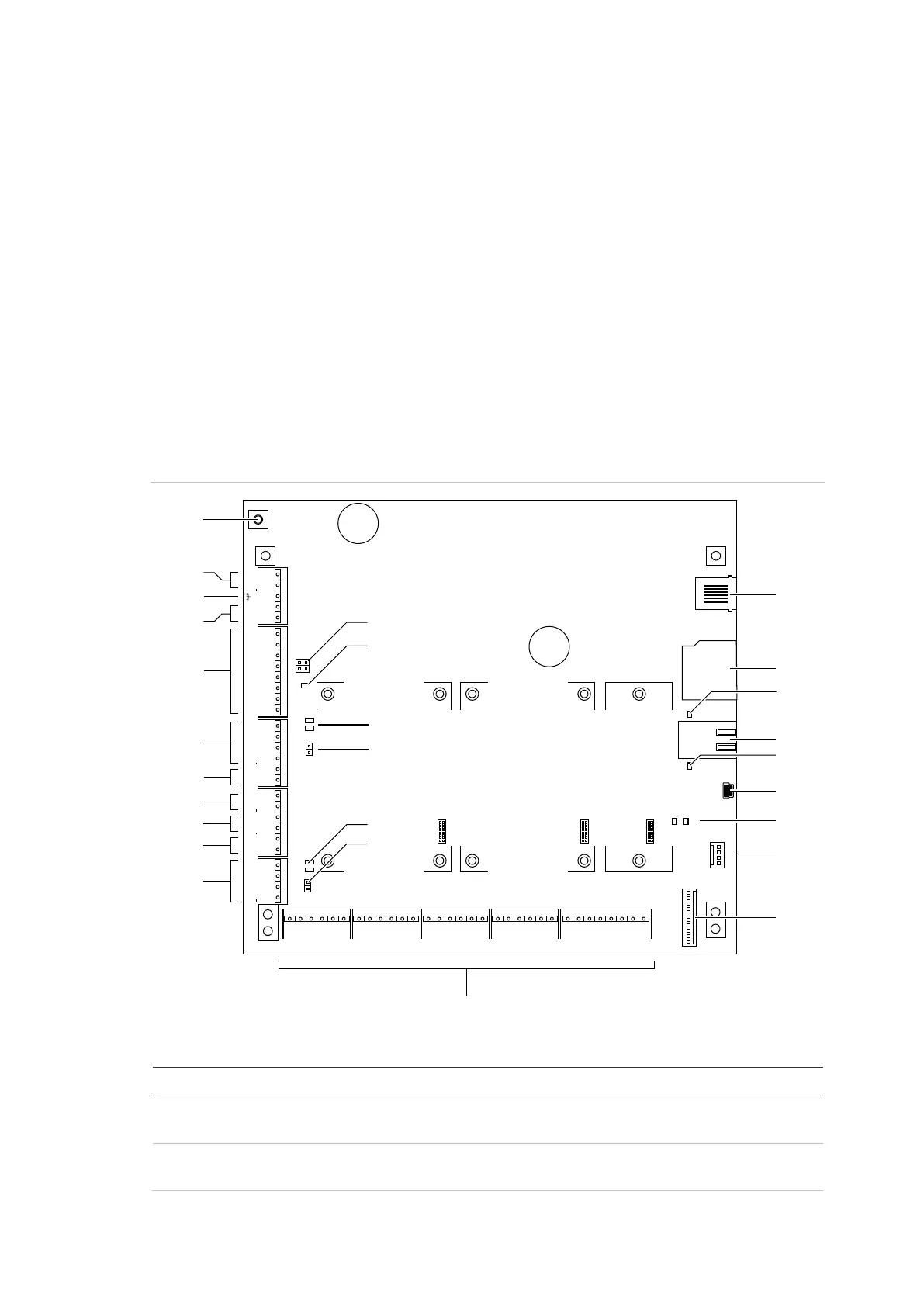
See Figure 5 below for the locations of connectors and other items. See “Cabling
requirements” on page 2 for recommendations for the application and wiring of
Challenger equipment.
Figure 5: Challenger10 board details
Figure 5 legend
Item Description
1. Connect one end of each LAN cable shield to the ring terminal and fasten with M3 screw
to the Challenger panel board’s LAN earth terminal.
2. Connect the power terminals to a 16 Volt AC plug pack. Maximum current drawn by the
panel with no peripheral devices connected is approximately 200 mA.
+12
Rx
Tx
0V
TERM2
TERM1
TEST
Expander 1 Expander 2 Expander 3
C1 C2 C3 C4 C5 C6 C7 C8 C9 C10 C11 C12 C13 C14 C15 C16
ALARM INPUTS
J6
J14
~AC~
J15
BATT
AUX POWER COMMS 1
TAMPER
D+ D T C S+ S S+ S
EXT INT
STRB COMMS 2
D+ D
J18 J19 J20 J17
J1 J2 J3 J4 J5
J7 J8 J9 J10
L1
TX1 RX1
TX2 RX2
RX0
TX0
1
2
–
+
+ + + +
– – – –
+
–
+
–
+
–
Link
Active
100BT
(2)
(3)
(4)
(5)
(6)
(7)
(8)
(9)
(10)
(1)
(11)
(12)
(13)
(14)
(16)
(18)
(21)
(20)
(19)
(24)
(25)
(26)
(27)
(23)
(22)
(15)
(17)