18 Challenger10 Installation and Quick Programming Manual
Telephone connection
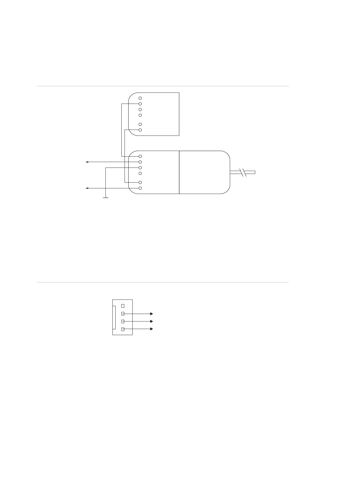
See Figure 5 on page 11, item 13. The Challenger panel is supplied with a pre-
wired 604 plug for connection to a 611 socket for PSTN in connection mode 3 for
dialler reporting formats (see Figure 11 below).
Figure 11: Line connections for 611 socket for dialler reporting formats
J15 serial port
See Figure 5 on page 11, item 20. The J15 port (also called STU port) may be
used for connection to a management software computer or to a printer.
Figure 12 below details the required connections from the J15 terminals to either
a DB9 or a DB25 serial connector (to a management software computer).
Figure 12: Wiring details for computer connection
LED indications
Refer to Figure 5 on page 11:
• L1 (item 23) flashes slowly to indicate normal panel operation, and flashes
quickly during reset mode (“Clearing the memory via the Challenger panel
PCB” on page 24) or firmware update (“Firmware upgrade process” on
page 32).
• Tx0 (item 19) flashes to indicate data being sent from the Challenger to a
device connected to J15 (serial port). On solid when J15 is ready
(inactive).
1
2
3
4
5
6
Pins 2 and 6
to telephones
on premises
Connection mode 3
Comms earth
604 plug connected
to Challenger panel
611 socket
Pins 2 and 6
to PSTN
1
2
3
4
5
6
+12
Rx
Tx
0V
J15 on Challenger PCB
Tx
Rx
GND
Computer serial port
3
2
5
2
3
7
DB9 pins: DB25 pins: