Challenger10 Installation and Quick Programming Manual 17
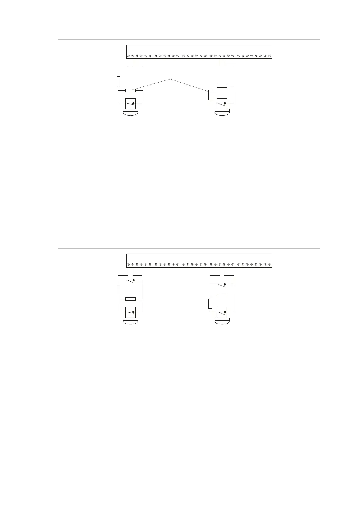
Figure 9: Wiring of key switches for input types 6 and 31
Input type 6 is used for momentary area control.
• 10 kΩ (normal state of key switch) indicates sealed.
• 5 kΩ or 20 kΩ indicates unsealed (the programmed alarm group functions are
performed).
Input type 31 is used for toggling area control. When the input switches to
unsealed, the areas secure. When the input seals, the areas are in access.
• 10 kΩ (normal state of key switch) indicates sealed (turn areas off).
• 5 kΩ or 20 kΩ indicates unsealed (turn areas on).
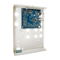
Figure 10: Wiring of key switch and alarm contact for input type 33
Input type 33 (24-hour alarm & isolate input) is used to wire a key switch and an
alarm contact to the same input. For example, a key switch used to isolate a
shop’s input in a shopping centre where only one input is available for each shop.
Alarm is generated when input changes from sealed to open or short.
• 10 kΩ (normal state of key switch) indicates sealed
• 5 kΩ or 20 kΩ indicates unsealed (isolated, no alarm generated)
• Open circuit generates a tamper alarm
• Short circuit generates an alarm
C1 C2 C3 C4 C5 C6 C7 C8 C9 C10 C11 C12 C13 C14 C15 C16
10K
10K
Normally closed
10K
Normally open
key switch contact
10K
Not used with
two-state monitoring
C1 C2 C3 C4 C5 C6 C7 C8 C9 C10 C11 C12 C13 C14 C15 C16
10K
10K
Normally closed
10K
Normally open
10K
Normally open
alarm contact
Normally open
alarm contact