Challenger10 Installation and Quick Programming Manual 13
Item Description
23. LED 1 flashes slowly to indicate panel operation, and flashes quickly during firmware
update or panel default.
24. Transmit and receive LEDs to indicate activity on LAN 1. See “LED indications” on page
18.
25. TERM link for LAN 1. See “Terminating the RS-485 LAN” on page 14.
26. Transmit and receive LEDs to indicate activity on LAN 2. See “LED indications” on page
18.
27. TERM link for LAN 2. See “Terminating the RS-485 LAN” on page 14.
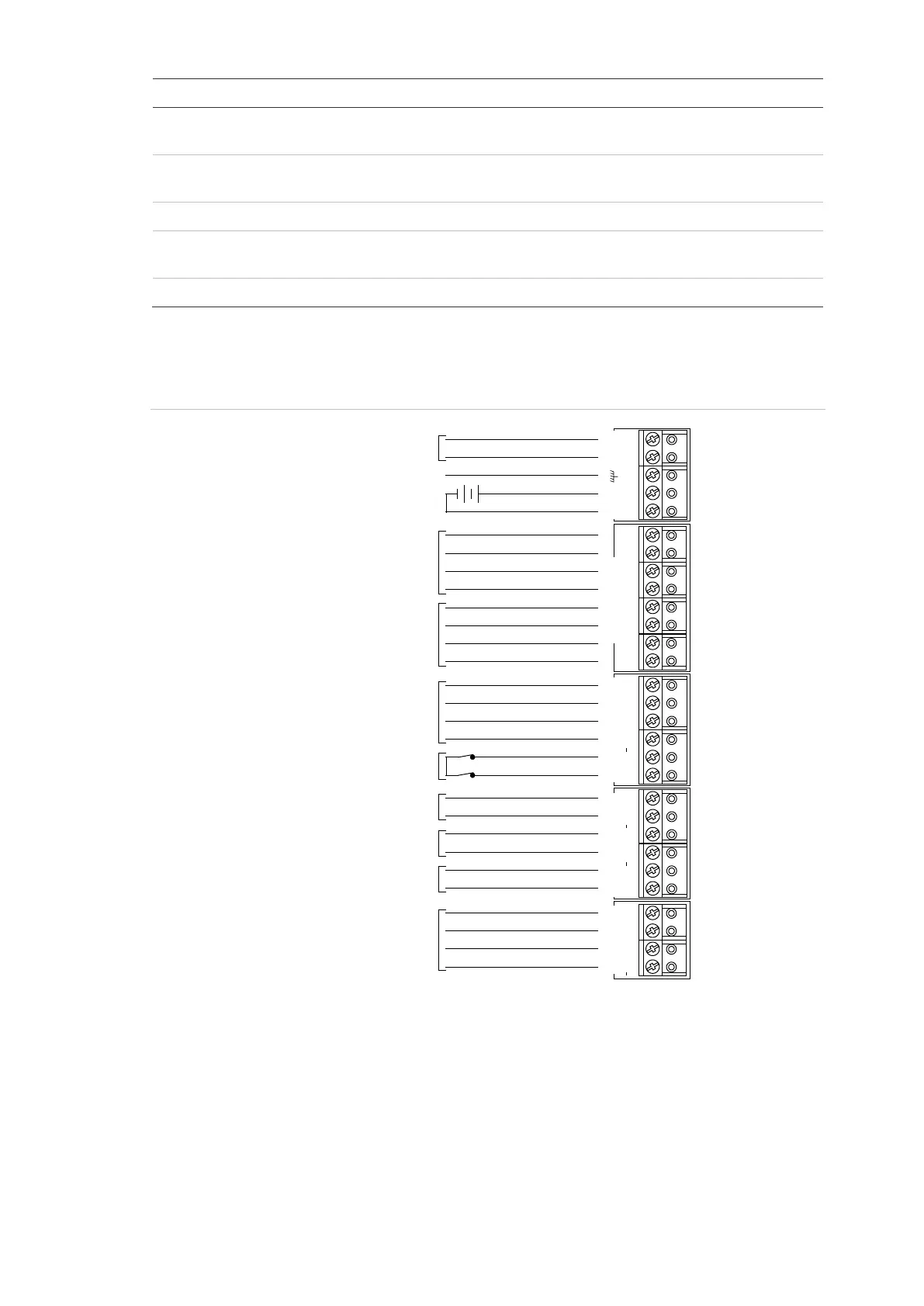
See Figure 6 below for connection details for terminal blocks J1 to J5.
Figure 6: Connection details for terminal blocks J1 to J5
16 VAC plug pack
Notes
• Use the 16 VAC plug pack supplied with the Challenger panel.
• When installing plug packs, do not power the unit until you have terminated all
necessary wires and checked that you do not have a short circuit. Fused plug
packs cannot be replaced under warranty as the fuse operation can only be
caused by a direct short circuit.
Plug pack earth wire
16 VAC plug pack
12 V battery
Auxiliary power 12 VDC +
Auxiliary power 12 VDC –
LAN 1 (required)
RS-485 data cable
Panel tamper switch
External 8 siren speaker
or 1K 1/4 watt resistor
Ω
Ω
Internal 8 siren speakerΩ
12 V strobe
LAN 2 (optional)
RS-485 data cable
~AC~
BATT
AUX POWER COMMS 1
TAMPER
D+ D T C S+ S S+ S
EXT INT
STRB COMMS 2
D+ D
–
+
+ + + +
– – – –
+
–
+
–
+
–