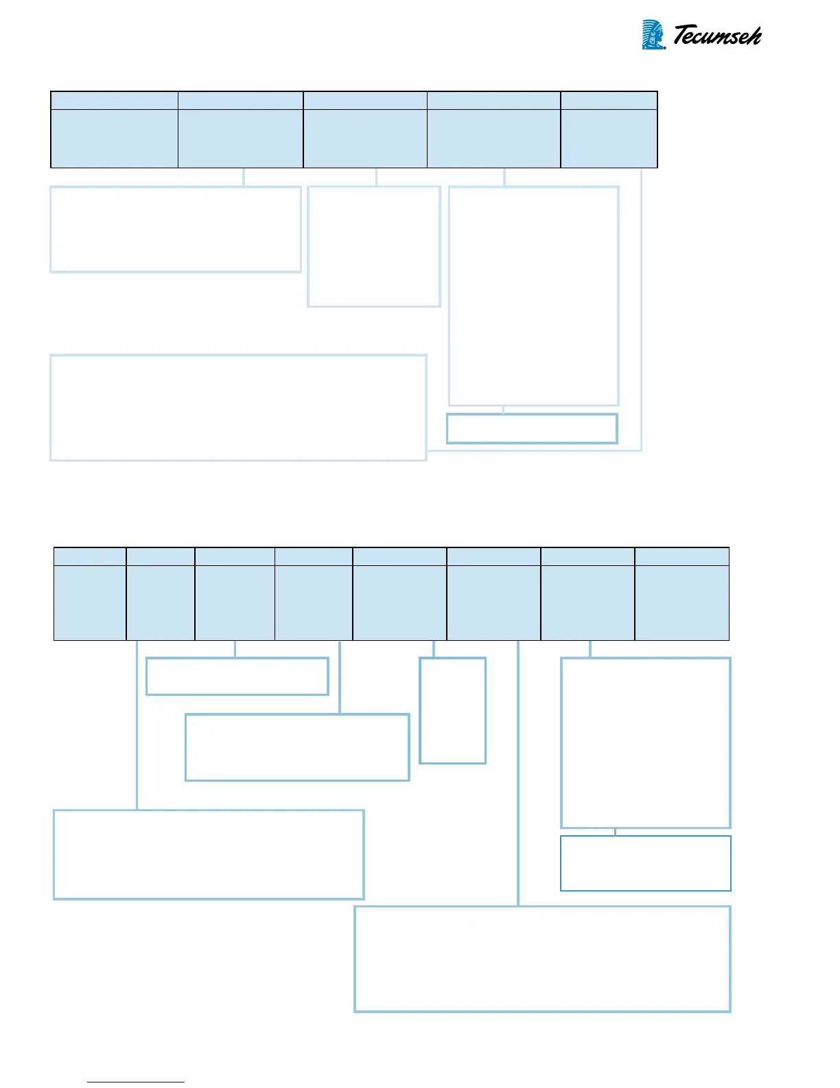
23
3ARR3- A 5 C 3
POTENTIAL
RELAY TYPE
NUMBER OF
TERMINALS AND
BRACKET
COIL GROUP
(CONTINUOUS
VOLTAGE)
CALIBRATION
(HOT PICKUP)
(VOLTS)
MOUNTING
POSITION
2 = 168
3 = 332
4 = 502
5 = 253
6 = 420
7 = 130
8 = 214
10 = 375
21=148
22=194
23=292
24=383
25=450
26=479
27=564
28=530
A = 5 screw terminal "L" bracket
B = 5 screw terminal flat bracket
C = 3 screw terminal "L" bracket
D = 3 screw terminal flat bracket
U = 5 quick connect terminal "L" bracket
A = 260-280
B = 280-300
C = 300-320
D = 320-340
E = 340-360
F = 350-370
G = 360-380
H = 365-395
J = 120-130
K = 130-140
L = 140-150
M = 150-160
N = 160-170
P = 170-180
R = 180-190
S = 190-200
T = 200-220
U = 220-240
V = 240-260
W = 210-230
BA=290-310
BB=110-120
TP=170-180
TV=240-260
TW=210-230
NOTE: Room temperature calibration
is 5 to 7% lower than these values.
See note on page 22.
1 = Face down
2 = Face up
3 = Face out - numbers horizontal
4 = Face out - rotated 90° clockwise from number 3 position
5 = Face out - numbers upside down - horizontal
6 = Face out - rotated 90° counterclockwise from number 3 position
Example: 3ARR3-A5C3
FIGURE 3-14: Explanation of GE Potential Relay Code.
128- 12 2- 13 3 5 C A
POTENTIAL
RELAY
TYPE
TYPE OF
BRACKET
CONTACT
STRUCTURE
TERMINALS,
TYPE AND
LOCATION
COIL GROUP
(CONTINUOUS
VOLTAGE)
MOUNTING
POSITION
CALIBRATION
(HOT PICK UP)
(VOLTS)
CUSTOMER'S
PART NUMBER
(TO BE
STAMPED ON
RELAY)
1 = 130
2 = 170
3 = 256
4 = 336
5 = 395
6 = 420
7 = 495
2 = SPNC - less than 1½ HP
6 = SPNC - 1½ and larger
11 = 3 screw terminal
12 = 4 screw terminal (seldom used)
13 = 5 screw terminal
23 = 5 quick connect terminals
See note on page 22.
1 = Face down
2 = Face up
3 = Face out - numbers horizontal
4 = Face out - rotated 90° clockwise from number 3 position
5 = Face out - numbers upside down - horizontal
6 = Face out - rotated 90° counterclockwise from number 3 position
11 = Flat bracket remote (Tecumseh)
12 = "L" bracket (Tecumseh)
16 = "L" bracket for "FB" model compressors
20 = "L" bracket for Tecumseh Twins = 1½ HP and larger
21 = "L" bracket for capacitor box mounting
29 = Flat bracket (Marion) was "14" (under cover)
A = 260-280
B = 280-300
C = 300-320
D = 320-340
E = 340-360
F = 350-370
G = 360-380
H = 365-395
J = 120-130
K = 130-140
L = 140-150
M = 150-160
N = 160-170
P = 170-180
R = 180-190
S = 190-200
T = 200-220
U = 220-240
V = 240-260
W = 210-230
NOTE: Room temperature
calibration is 5 to 7% lower
than these values.
Example: 128-122-1335CA
FIGURE 3-15: Explanation of White Rodgers Potential Relay Code.