43
Checking for Other Electrical Problems in Single-phase Motors
This section provides procedures for checking the components such as the thermal pro-
tector, relay and capacitor in a single-phase compressor. Table 4-3 (below) can be used
to locate the appropriate procedure for the compressor you are servicing. Examine the
compressor and determine presence and/or the type of:
• Thermal protector (internal or external)
• Relay (current, potential or PTC)
• Capacitor(s) (start or run)
With that information, use Table 4-3 to determine the location of the procedure for the
compressor you are servicing.
For more information on:
• Compressor motor types, see “Single-phase Compressor Motor Types” on pages 16-
17.
• Thermal protectors, see “Hermetic Compressor Thermal Protectors” on page 19.
• Starting relays, see “Compressor Motor Starting Relays” on pages 21-24.
• Capacitors, see “Selecting Capacitors” on pages 24-26.
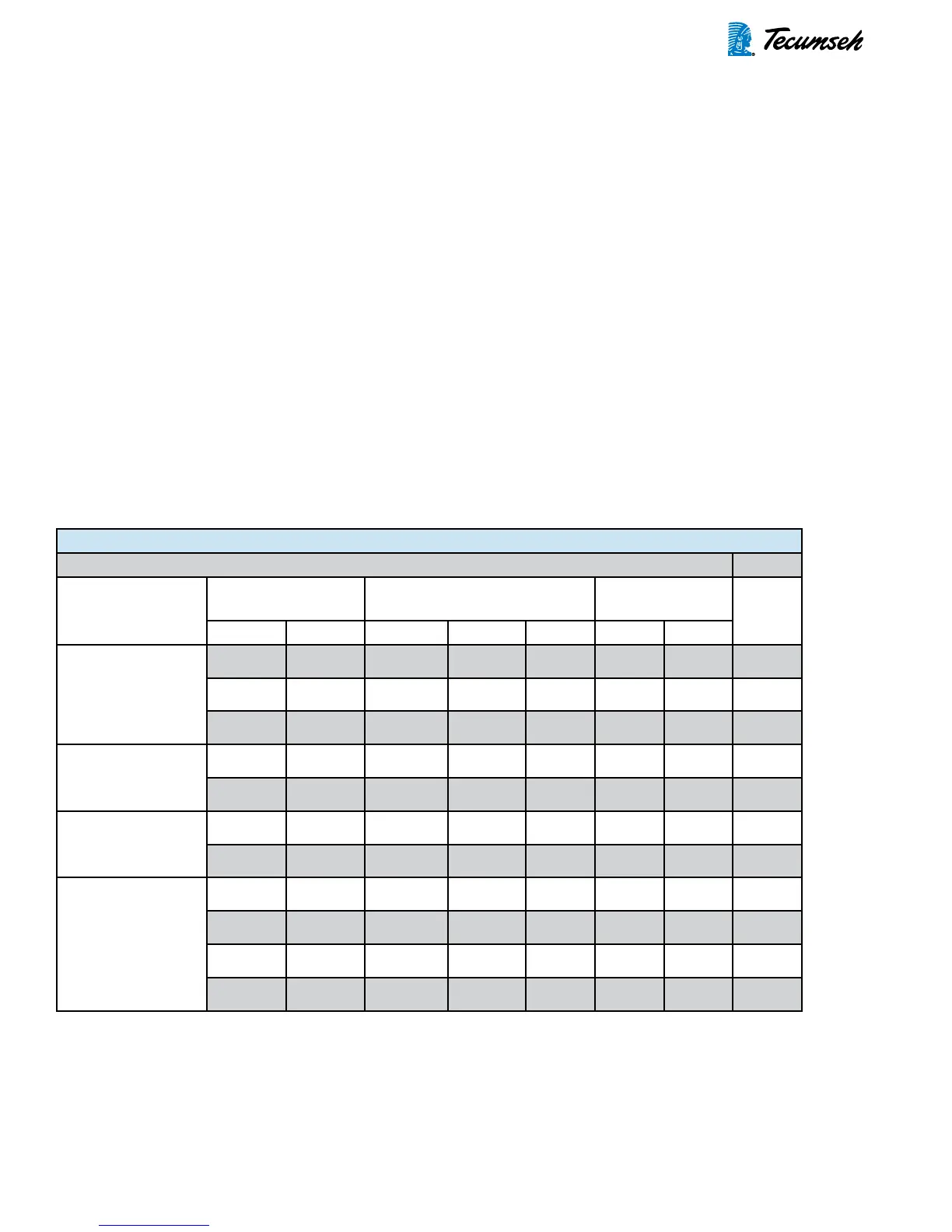
Table 4-3: Locating Service Procedures by Component Types
If your compressor has: Go To:
Compressor Motor
Type
Thermal Protector
Type
Relay Type Capacitor Type
Page
Internal External Current Potential PTC Run Start
Resistance Start In-
duction Run (RSIR)
(Split-Phase)
√ √
44
√
WIRED
46
√
MODULE
48
Capacitor Start In-
duction Run (CSIR)
√ √ √
50
√ √ √
53
Capacitor Start and
Run (CSR)
√ √ √ √
56
√ √ √ √
59
Permanent Split
Capacitor (PSC)
√ √
62
√ √
64
√
WIRED
√
66
√
MODULE
√
68
 Loading...