26
TROUBLESHOOTING
ENGINE OVERSPEEDING
1. If the engine runs wide open (faster than normal), shut the engine off or slow it down immediately.
2. Visually inspect the air vane, linkage, carburetor throttle shaft, and speed control for debris blockage, binding,
breakage, or incorrect hook-up. Check the governor spring for a stretched or distorted condition. To view the
components, remove the recoil assembly and/or fuel tank if necessary. For information on the proper linkage or
spring connections, review the appropriate diagrams in this section.
3. Clean, correct or replace binding or damaged parts. Set the speed control to the recommended engine R.P.M.
ENGINE SURGING
1. Try to stabilize the engine R.P.M. by holding in one position the carburetor throttle shaft on the exterior of the
carburetor.
2. If the engine R.P.M. stabilizes, the governor or governor adjustment should be checked. Follow the procedure under
"Governor Adjustment" in this chapter. If the engine R.P.M. does not stabilize, the engine will require additional
checks. Some surging problems can be carburetor or fuel related. Additional information can be found in the
troubleshooting section of Chapter 3.
3. If the problem persists after the governor adjustment, check the engine R.P.M. found on microfiche card # 30 or in
the computer parts lookup. If the setting for high and low speed are within the listed specification and a slight surge
is experienced, increasing the engine idle speed slightly may eliminate this condition.
4. Visually inspect the air vane, linkage, carburetor throttle shaft, and speed control for debris blockage, binding,
breakage, or incorrect hook-up. Check the governor spring for a stretched or distorted condition. To view the
components, remove the recoil assembly and/or fuel tank if necessary. For information on the proper linkage or
spring connections, review the appropriate diagrams in this section.
SERVICE
For governor disassembly or assembly procedures see "Service" in Chapter 7.
GOVERNOR ADJUSTMENT
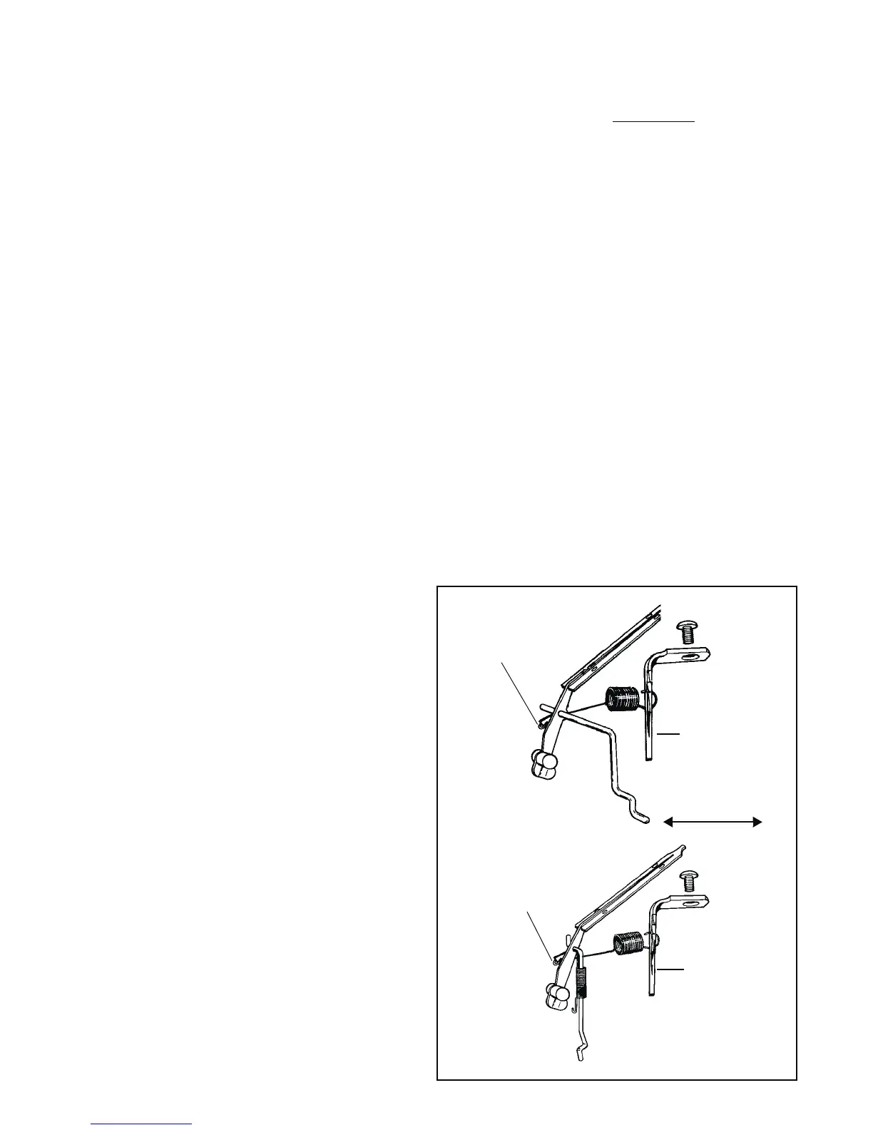
Three different styles of governor systems are used on
TC/TM engines. Use the following illustrations (diags. 4-3,
4-4 and 4-5) to identify the governor system used and the
following procedure to adjust the governed engine speed.
1. Allow the engine to run for at least 5 minutes to reach
the operating temperature. Make sure the air filter
(if equipped) is clean and the choke is in the off
position.
2. Using a Vibratach (part #670156) or other
tachometer, determine the engine's R.P.M at idle and
wide open throttle. Consult microfiche card # 30 or the
computer parts lookup to obtain the recommended
engine speeds.
3. Using the applicable illustration, either bend the
speed adjusting lever toward the spark plug end of
the engine to decrease high speed R.P.M., or bend
the lever in opposite direction to increase R.P.M. On
TC Type II/TM engines, turn the speed adjusting
screw out to increase or in to decrease engine high
speed R.P.M. If the speed adjustment screw is turned
out to increase the engine R.P.M., the speed control
lever must be moved to allow the speed control
plunger to contact the speed adjustment screw.
4. The low speed is set by moving the throttle control to
the lowest speed position and adjusting the low speed
adjustment screw on the carburetor.
Speed
Adjusting
Lever
Speed
Adjusting
Lever
TC TYPE I
TC TYPE I and
EARLY TC TYPE II
4-3
Spring Hooked
In Notch
Spring Hooked
In Notch
Decrease Increase
 Loading...