9
• Locate the Crossbrace Hardware Kit (HK1011)
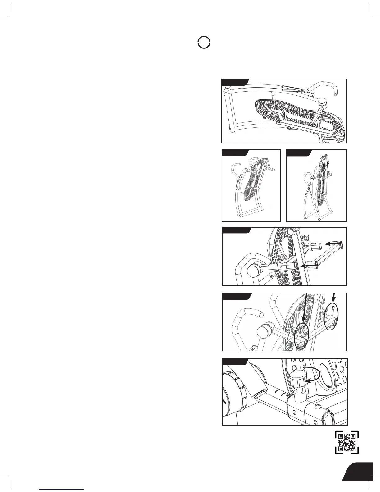
• To stand the inversion table upright, first move the A-Frame onto
its side (Figure 11), and then carefully lift it up onto its feet (Figure 12).
• Use the handles to open the A-Frame wide enough so that it is stable
and can stand upright on its own (Figure 13).
• Align the holes in the Crossbrace with the last hole on the Rotation
Adjustment Arms (Figure 14).
• Insert the Chicago Posts and secure with the Chicago Screws,
tightening with the Allen Wrenches provided (Figure 15).
NOTE: Due to the tapered style of the Chicago Post, it may not sit flush
against the Crossbrace.
• Turn the Pinlock Knobs clockwise to re-engage the “de-rattler” function
(Figure 16).
STEP
4
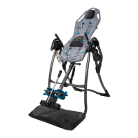
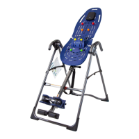
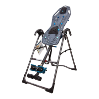
Attach Crossbrace to Rotation Adjustment Arms
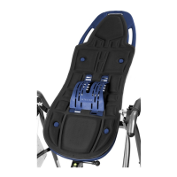
The Contour L5 is shown here. Your actual model may vary.
FIGURE 13
FIGURE 16
FIGURE 15
FIGURE 14
FIGURE 11
FIGURE 12