11VORTEK Doc.# VT5 OM 050499, Rel. 2.1
Chapter 3 Startup Adjustments
ing either on the duct or on a wall, column, or other support close to the point of
measurement. The transmitter housing is a general purpose enclosure and is
therefore not designed for mounting outdoors or in areas requiring explosion-
proof classification. For outdoor use, a Nema 4 enclosure can be purchased as
an option. For installation in explosion-proof areas contact factory. Areas where
the temperatures are expected to exceed 125° F for extended periods of time are
to be avoided.
2.3 Probe and Transmitter Connection
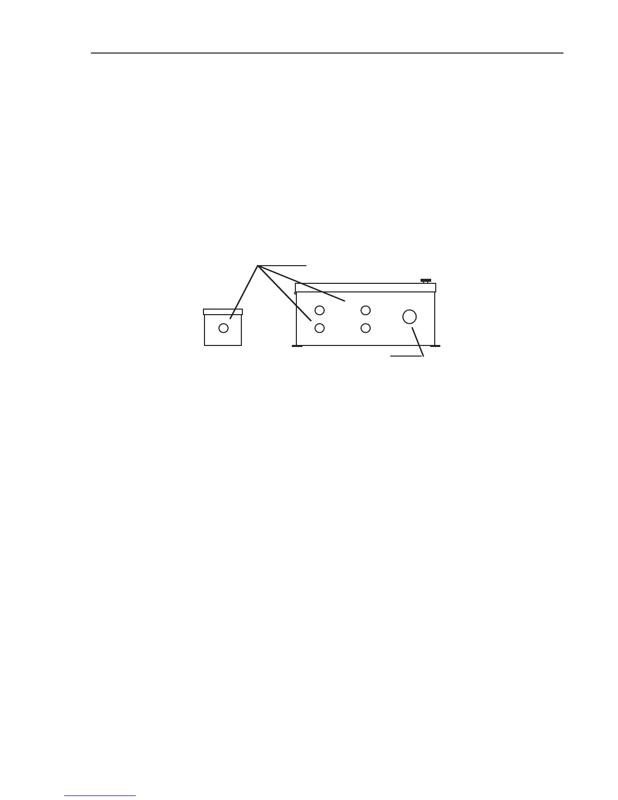
Probe Connection- Ten foot connecting cables are provided for each insertion probe.
This cable has a shielded 8 pin connector from the probe electronics enclosure and is
plugged into either connector on the bottom of the transmitter.
12
34
CABLE CONNECTORS
CONDUIT ENTRY
TRANSMITTER
Probe Cable Connection Points
Figure 1
Probes should be plugged in to the transmitter in numeric sequence (ie. 1, 2, 3, 4). If one
probe is used it should be plugged into connector 1. If three probes are used they should
be plugged into connectors 1, 2, and 3. It is not important however which probe is plugged
in to a particular connector. After connectors have been plugged in it is advisable to an-
chor them with tie wraps.
2.4 Transmitter Wiring
Terminations- Inside the transmitter on the bottom right are two pairs of terminals. The
left most pair are the signal output terminals. (See Fig. 3) The right most are for 24VAC
Power input. Transmitter power is 24 Volts AC, 8VA maximum current. Power may fluctu-
ate ±20% without effect.
Signal and power wiring can be run in a common shielded cable or separately. If run
separately, signal cable should be shielded. In either case, shields should be tied to the
input device (controller) common and taped back on the other end. (See Fig. 2) Typically,
shields are terminated at the controller.
Output Signal- Transmitter output is 4-20mA and is capable of driving up to 650 ohms of
load. Control equipment which accepts voltage inputs can be accommodated with internal
jumpers that will generate a 1-5VDC output or a 2-10 VDC output. SEE DRAWING ON
NEXT PAGE.
 Loading...