17VORTEK Doc.# VT5 OM 050499, Rel. 2.1
Chapter 4 Calibration and Maintenance
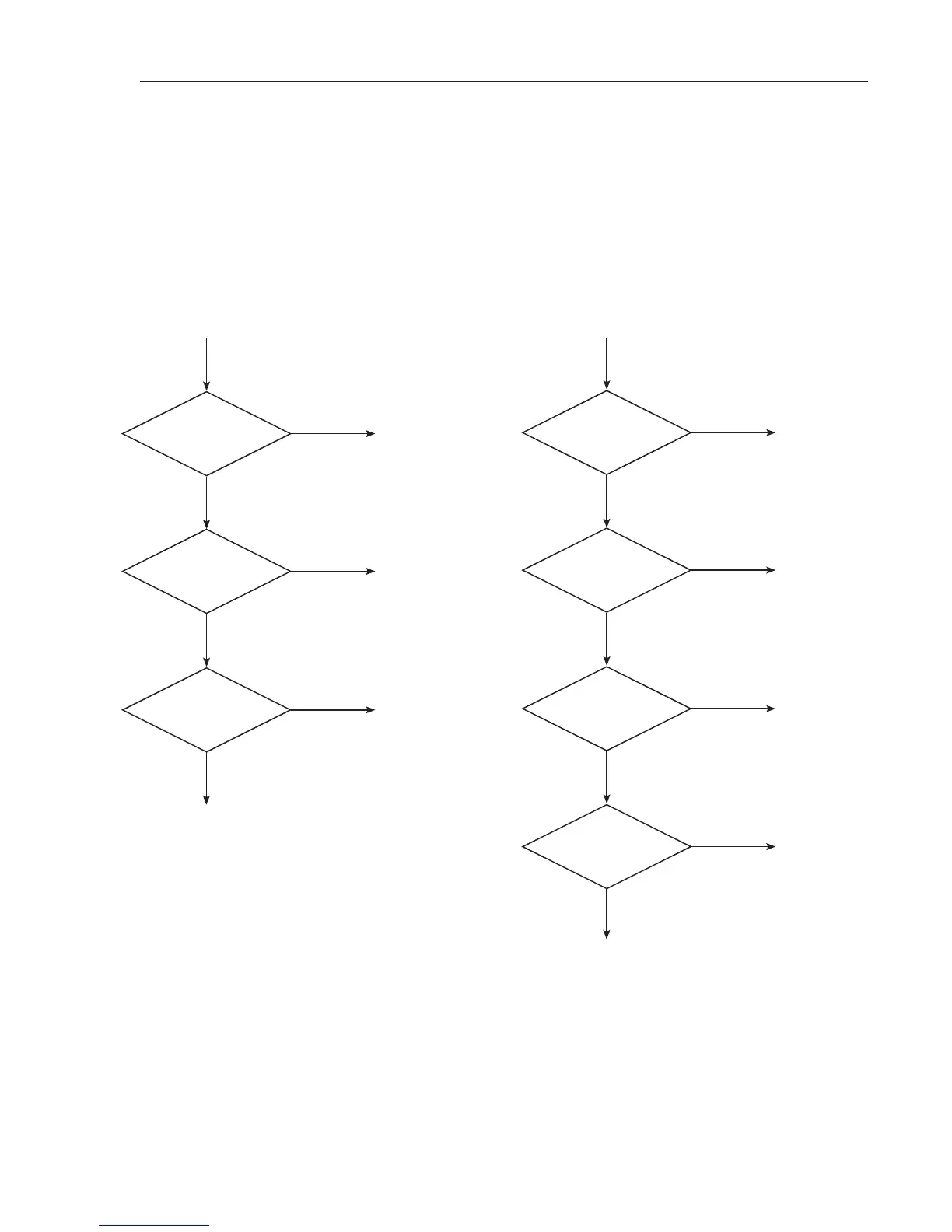
4.6 Trouble Shooting
The following flow charts are designed to aid in trouble shooting the transmitter
and flow sensors should problems be experienced in commissioning the airflow
measurement system.
No Signal
Output
24VAC
Present
Output
Polarity Correct?
No
_
Output
w/signal lines connected
Output w/signal lines
Disconnected
Correct
Power
(Maintain Polarity)
Correct
Polarity
Contact
Tek-Air Systems
for Assistance
Correct possible signal
transmission line problems
a. Open Circuit
b. Loop resistance above 650 Ohms
c. Short to ground in “+” wire
Yes
Yes
Yes
No
No
No
Output Signal
always at 4mA
Flow Above
350 FPM with
Linear Profile?
DIPs
Set to Operate?
Probe Cables
Plugged in?
Establish
Flow in Duct
Set as Follows:
1-Either ON or OFF
2-ON
3-OFF
4-OFF
Plug in
Cables
Contact Tek-Air Systems
for Assistance
Yes
Yes
Yes
No
No
No
Probes in
Backwards?
No
Yes
Reinstall in
Proper Direction
 Loading...