12VORTEK Doc.# VT5 OM 050499, Rel. 2.1
24 VAC
POWER
- +
4-20ma
OUTPUT
INPUT
+ -
24VAC
POWER
SHIELD
Tape Back Drain Line
at Transmitter &
Tie to Controller Common
CONTROLLER COMMON
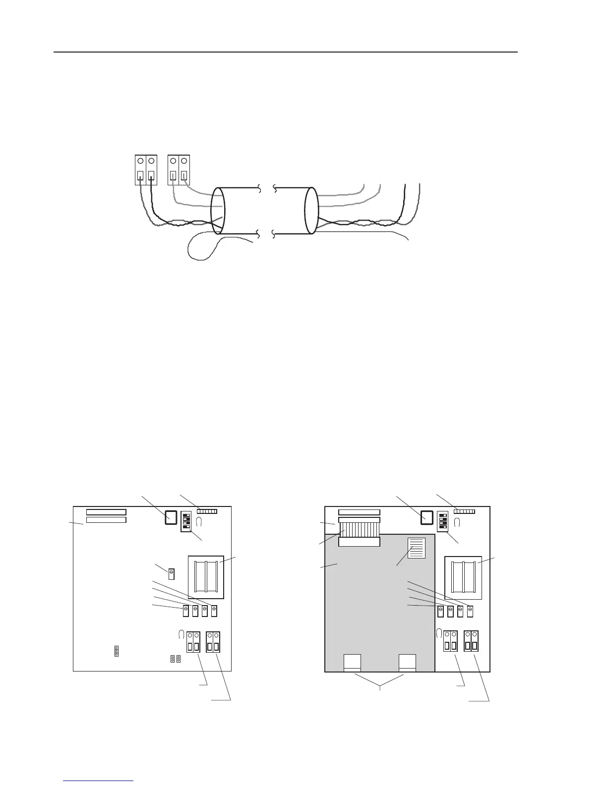
Transmitter Power and Signal Wiring
Figure 2
3.0 STARTUP ADJUSTMENTS
3.1 General Description
The VorTek airflow transmitter has several modes of operation which are deter-
mined by setting the four position DIP (Dual Inline Package) switch located on the
upper right corner of the mother board. This switch is utilized for adjusting the damp-
ing, transmitter zero check, and quick calibration check.In addition to this switch,
potentiometers are available for adjusting Transmitter Zero, Full Scale, Frequency
Offset, and digital indicator output. See Figure 3 below.
Chapter 3 Startup Adjustments
Figure 3 - Vortek Mother Board, (left); VorTek mother board showing Amplifier board installed (right).
POWER
DISPLAY
OUTPUT
SETUP
DIP
PROGRAM
MODULE
PROBE BAR INPUTS
SIGNAL
JUMPERS
AMPLIFIER
BOARD
MOTHER
BOARD
RIBBON
CABLE
ZERO
SPAN
OFFSET
DISPLAY
TP5
TRANSFORMER
TP1
ZERO
SPAN
OFFSET
DISPLAY
DISPLAY
OUTPUT
SETUP
DIP
PROGRAM
MODULE
SIGNAL
POWER
JP1 (3-pin)
THRESHOLD POT.
MOTHER
BOARD
JP2 JP3
TRANSFORMER
TP5
TP1
 Loading...