13VORTEK Doc.# VT5 OM 050499, Rel. 2.1
Chapter 4 Calibration and Maintenance
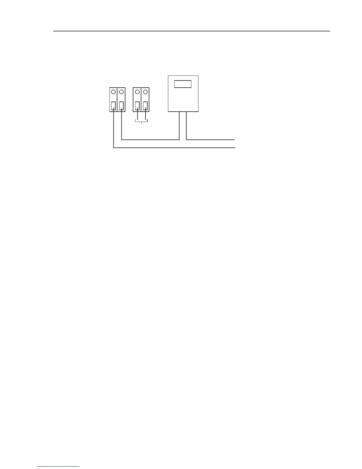
Transmitter output checks can be made by connecting a voltmeter set for DC
milliamps, in series as follows;
24VAC
2.34
- +
+ -
+
-
SIGNAL WIRES
SIGNAL POWER
DVM
Figure 4
3.2 Normal Operation
In order for the transmitter to function properly as a flow measurement device the DIP
switch must be set as follows;
DIP 1 On or Off
DIP 2 On
DIP 3 On
DIP 4 Off
3.3 Damping Adjustment
Damping can be set by using DIP switch number 1. With switch one in the “on” position minor
damping is in effect. With switch one in the “off” position the normal damping is doubled.
3.4 Zero Check
Transmitter zero output (4-20mA) can be simulated by setting DIP switches 2, 3, and 4
as follows, and removing the probe connectors from the bottom of the transmitter;
DIP 1 On or Off
DIP 2 Off
DIP 3 Off
DIP 4 Off
With the voltmeter set for milliamps and connected in series (See fig. 4) with the 4-
20mA output, the zero-flow output can be adjusted by utilizing the zero calibration
potentiometer. At these settings the meter should read 4mA. Reinstall the probe con-
nectors when complete. Remember to return DIP switches to normal operation or
continue on to Quick Calibration Check.
 Loading...