EasyManuals Logo

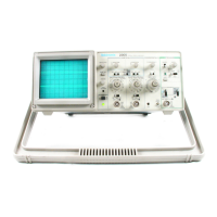
Tektronix 2205 Operator's Manual

Tektronix 2205
94 pages
To Next Page IconTo Next Page
To Previous Page IconTo Previous Page
Page #28 background imageLoading...
Page #28 background image
Operation
Table
2-1
Summary
of
Corttrols,
Connectors,
and
Indicators
No.
Title
Function
Recommended
Use
1
INTENSITY
Adjusts
trace
brightness.
Compensate
for
ambient
lighting,
trace
speed,
trigger
frequency.
2
BEAM
FIND
Compresses
display
to
within
CRT
limits
Locate
off-screen
phenomena.
3
FOCUS
Adjusts
for
finest
trace
thickness.
Optimize
display
definition.
4
TRACE
ROTATION
Adjusts
trace
parallel
to
center¬
line.
Compensate
for
earth's
magnetic
field.
5
POWER
Turns
power
on
and
off.
Control
power
to
the
instrument.
6
Power
indicator
illuminates
when
power
is
turned
on.
Determine
power
condition.
VERTICAL
POSITION
Moves
trace
up
or
down
on
screen.
Position
trace
vertically
and
compensate
for
dc
component
of
signal.
9
CH
1~BOTH-
CH
2
Selects
signal
inputs
for
display.
View
either
channel
independently
or
both
channels
simuitaneously.
10
NORM-
INVERT
Inverts
the
Channel
2
signal
display.
.
Provide
for
differential
(CH
1-CH
2)
or
summed
(CH
1+CH
2)
signals
when
ADD
is
selected.
11
ADD-ALT-
CHOP
ADD
shows
alge¬
braic
sum
of
CH
1
and
CH
2
signals.
ALT
displays
each
channel
alternately.
CHOP
switches
be¬
tween
CH
1
and
CH
2
signals
during
the
sweep
at
500
kHz
rate.
Display
summed
or
indi¬
vidual
signals.
12
VOLTS/DIV
Selects
vertical
sensitivity.
Adjust
vertical
signal
to
suitable
size.
2-2
2205
Operator’s

Other manuals for Tektronix 2205

Questions and Answers:

Question and Answer IconNeed help?

Do you have a question about the Tektronix 2205 and is the answer not in the manual?

Tektronix 2205 Specifications

General IconGeneral
BrandTektronix
Model2205
CategoryTest Equipment
LanguageEnglish

Related product manuals