Controls, Connectors, and Indicators-2465 Operators
VERTICAL
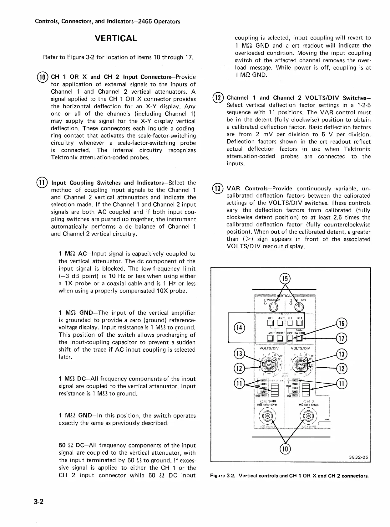
Refer to Figure
3-2
for location of items
10
through
17.
CH
1
OR
X
and CH
2
lnput Connectors-Provide
for application of external signals to the inputs of
Channel
1
and Channel
2
vertical attenuators. A
signal applied to the CH
1
OR
X
connector provides
the horizontal deflection for an
X-Y
display. Any
one or all of the channels (including Channel
1)
may supply the signal for the
X-Y
display vertical
deflection. These connectors each include
a
coding-
ring contact that activates the scale-factor-switching
circuitry whenever
a
scale-factor-switching probe
is
connected. The internal circuitry recognizes
Te ktronix attenuation-coded probes.
lnput Coupling Switches and Indicators-Select the
method of coupling input signals to the Channel
1
and Channel
2
vertical attenuators and indicate the
selection made. If the Channel
1
and Channel
2
input
signals are both AC coupled and if both input cou-
pling switches are pushed up together, the instrument
automatically performs
a
dc balance of Channel
1
and Channel
2
vertical circuitry.
1
MSt AC-Input signal is capacitively coupled to
the vertical attenuator. The dc component of the
input signal is blocked. The low-frequency limit
(-3
dB point)
is
10
Hz or less when using either
a
1X
probe or a coaxial cable and is
1
Hz or less
when using
a
properly compensated
1 OX
probe.
I
MSt GND-The input of the vertical amplifier
is
grounded to provide
a
zero (ground) reference-
voltage display. lnput resistance
is
1
MSt to ground.
This position of the switch allows precharging of
the input-coupling capacitor to prevent
a
sudden
shift of the trace if AC input coupling
is
selected
later.
1
MSt DC-All frequency components of the input
signal are coupled to the vertical attenuator. lnput
resistance
is
1
MSt to ground.
1
MSt GND-In this position, the switch operates
exactly the same as previously described.
50 St DC-All frequency components of the input
signal are coupled to the vertical attenuator, with
the input terminated by
50
i-2
to ground. If exces-
sive signal is applied to either the CH
1
or the
CH
2
input connector while
50
Ll
DC input
coupling is selected, input coupling will revert to
1
MSt
GND
and
a
crt readout will indicate the
overloaded condition. Moving the input coupling
switch of the affected channel removes the over-
load message. While power
is
off, coupling
is
at
1
Mi-2 GND.
Channel
1
and Channel
2
VOLTSIDIV Switches-
Select vertical deflection factor settings in
a
1-2-5
sequence with
11
positions. The VAR control must
be in the detent (fully clockwise) position to obtain
a
calibrated deflection factor. Basic deflection factors
are from
2
mV per division to
5
V per division.
Deflection factors shown in the crt readout reflect
actual deflection factors in use when Tektronix
attenuation-coded probes are connected to the
inputs.
@
VAR
Controls-Provide continuously variable, un-
calibrated deflection factors between the calibrated
settings of the VO
LTSID IV switches. These controls
vary the deflection factors from calibrated (fully
clockwise detent position) to
at
least
2.5
times the
calibrated deflection factor (fully counterclockwise
position). When out of the calibrated detent,
a
greater
than
(>)
sign appears in front of the associated
VOLTSID IV readout display.
N
b
I
I
-
-""
MODE
-+
-
>e
Figure
3-2.
Vertical controls and
CH
1
OR
X
and
CH
2
connectors.