Section
4-2465
Operators
OPERATING CONSIDERATIONS
This section contains basic operating information and
techniques that should be considered before attempting
to make any measurements with your instrument.
GRATICULE
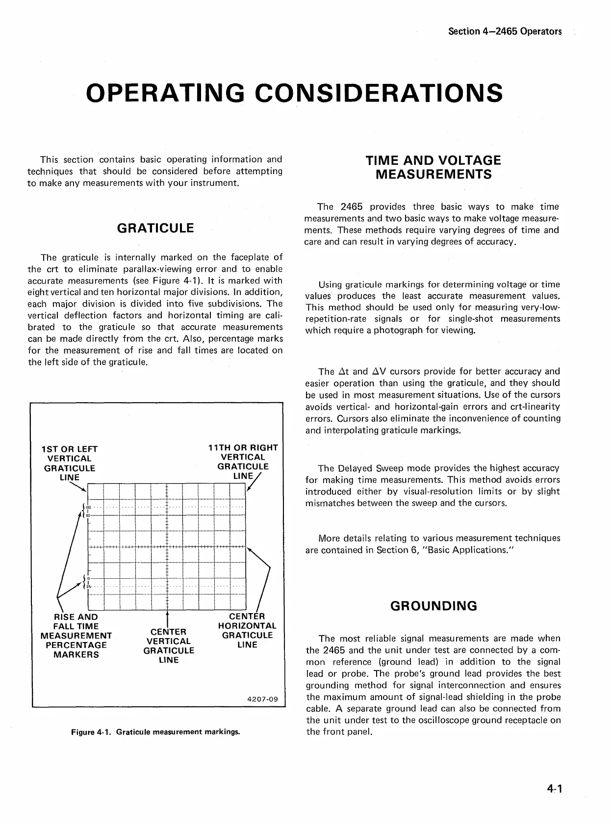
The graticule
is
internally marked on the faceplate of
the crt to eliminate parallax-viewing error and to enable
accurate measurements (see Figure
4-1).
It
is
marked with
eight vertical and ten horizontal major divisions. In addition,
each major division
is
divided into five subdivisions. The
vertical deflection factors and horizontal timing are cali-
brated to the graticule so that accurate measurements
can be made directly from the crt. Also, percentage marks
for the measurement of rise and fall times are located on
TlME AND VOLTAGE
MEASUREMENTS
The 2465 provides three basic ways to make time
measurements and two basic ways to make voltage measure-
ments. These methods require varying degrees of time and
care and can result in varying degrees of accuracy.
Using graticule markings for determining voltage or time
values produces the
least
accurate measurement values.
This method should be used only for measuring very-low-
repetition-rate signals or for single-shot measurements
which require a photograph for viewing.
the left side of the graticule.
The At and AV cursors provide for better accuracy and
easier operation than using the graticule, and they should
be used in most measurement situations. Use of the cursors
avoids vertical- and horizontal-gain errors and crt-linearity
errors. Cursors also eliminate the inconvenience of counting
and interpolating graticule markings.
1ST OR LEFT
VERTICAL
GRATICULE
Ll N E
RISE AND
FALL TlME
MEASUREMENT
I
CENTER
PERCENTAGE
VERTICAL
MARKERS
GRATICULE
LINE
1 ITH OR RIGHT
VERTICAL
GRATICULE
LINE/
CENTER
HORIZONTAL
GRATICULE
Ll N E
Figure
4-1.
Graticule measurement markings.
The Delayed Sweep mode provides the highest accuracy
for making time measurements. This method avoids errors
introduced either by visual-resolution limits or by slight
mismatches between the sweep and the cursors.
More details relating to various measurement techniques
are contained in Section
6,
"Basic Applications."
GROUNDING
The most reliable signal measurements are made when
the 2465 and the unit under test are connected by
a
com-
mon reference (ground lead) in addition to the signal
lead or probe. The probe's ground lead provides the best
grounding method for signal interconnection and ensures
the maximum amount of signal-lead shielding in the probe
cable.
A
separate ground lead can also be connected from
the unit under test to the oscilloscope ground receptacle on
the front panel.