Basic Applications-2465 Operators
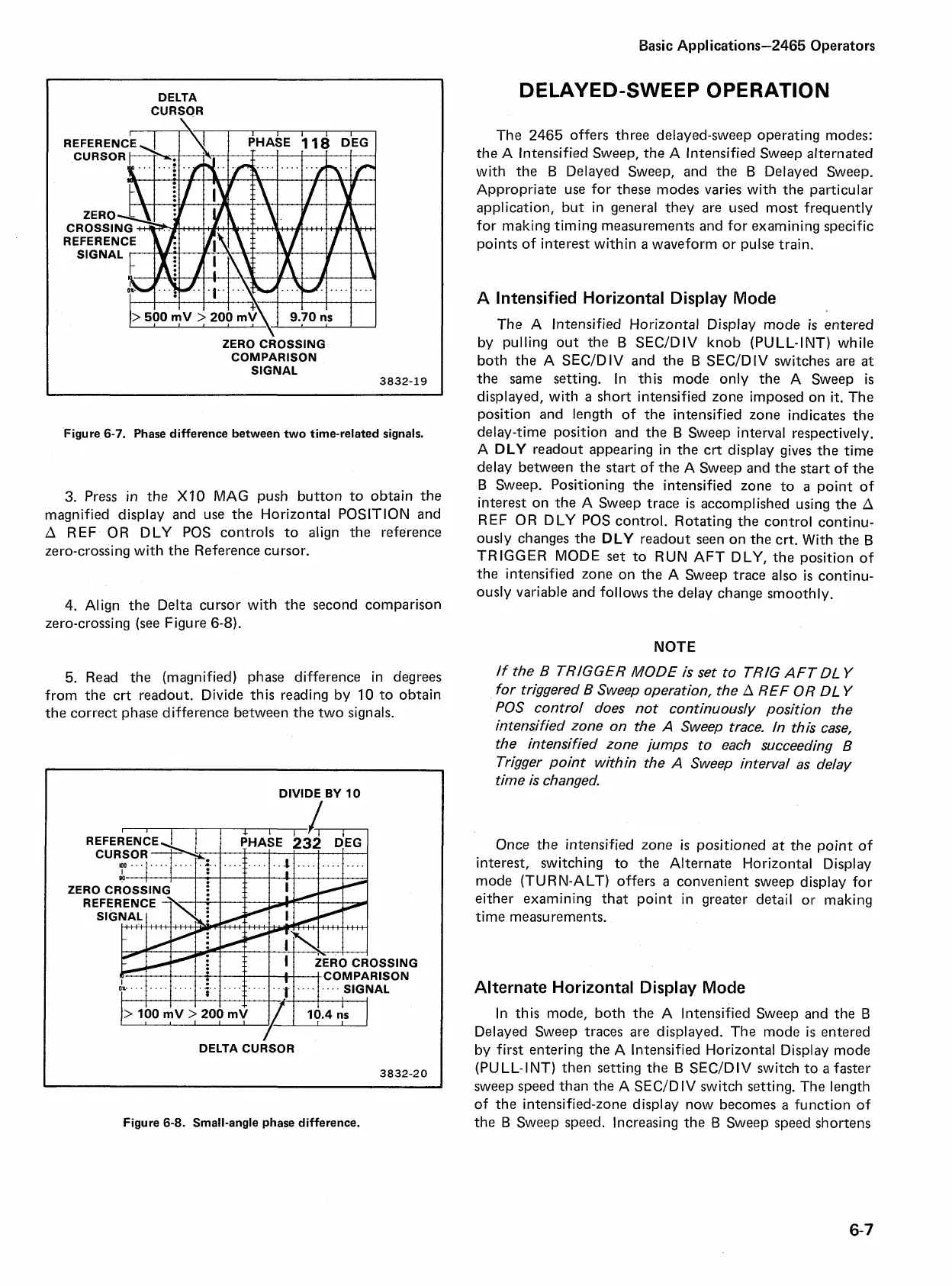
DELTA
CURSOR
ZERO CROSSING
COMPARISON
SIGNAL
Figure
6-7.
Phase difference between two time-related signals.
3.
Press in the
XI0
MAG push button to obtain the
magnified display and use the Horizontal POSITION and
A
REF OR DLY POS controls to align the reference
zero-crossing with the Reference cursor.
4.
Align the Delta cursor with the second comparison
zero-crossing (see Figure
6-8).
5.
Read the (magnified) phase difference in degrees
from the crt readout. Divide this reading by
10
to obtain
the correct phase difference between the two signals.
DIVIDE
BY
10
ZERO CROSSING
f
COMPARISON
. . . . SIGNAL
DELTA CURSOR
3832-20
Figure
6-8.
Small-angle phase difference.
DELAYED-SWEEP OPERATION
The
2465
offers three delayed-sweep operating modes:
the
A
lntensified Sweep, the A lntensified Sweep alternated
with the
B
Delayed Sweep, and the
B
Delayed Sweep.
Appropriate use for these modes varies with the particular
application, but in general they are used most frequently
for making timing measurements and for examining specific
points of interest within
a
waveform or pulse train.
A lntensified Horizontal Display Mode
The A lntensified Horizontal Display mode
is
entered
by pulling out the
B
SECIDIV knob (PULL-INT) while
both the A SECIDIV and the
B
SECIDIV switches are at
the same setting. In this mode only the A Sweep
is
displayed, with
a
short intensified zone imposed on
it.
The
position and length of the intensified zone indicates the
delay-time position and the
B
Sweep interval respectively.
A
DLY
readout appearing in the crt display gives the time
delay between the start of the A Sweep and the start of the
B
Sweep.
Positioning the intensified zone to a point of
interest on the A Sweep trace
is
accomplished using the
A
REF OR DLY POS control. Rotating the control continu-
ously changes the
DLY
readout seen on the crt. With the
B
TRIGGER MODE
set
to RUN AFT DLY, the position of
the intensified zone on the A Sweep trace also
is
continu-
ously variable and follows the delay change smoothly.
NOTE
If
the
B
TRIGGER MODE is set to TRIG
AFT
DL
Y
for triggered
B
Sweep operation, the
A
REF OR DL
Y
POS control does not continuowsly position the
intensified zone on the
A
Sweep trace. In this case,
the intensified zone jumps to each succeeding
B
Trigger point within the
A
Sweep interval as delay
time is changed.
Once the intensified zone
is
positioned at the point of
interest, switching to the Alternate Horizontal Display
mode (TURN-ALT) offers
a
convenient sweep display for
either examining that point in greater detail or making
time measurements.
Alternate Horizontal Display Mode
In this mode, both the A lntensified Sweep and the
B
Delayed Sweep traces are displayed. The mode
is
entered
by first entering the A lntensified Horizontal Display mode
(PULL-INT) then setting the
B
SECIDIV switch to
a
faster
sweep speed than the A SECIDIV switch setting. The length
of the intensified-zone display now becomes
a
function of
the
B
Sweep speed. Increasing the
B
Sweep speed shortens