Basic Applications-2465 Operators
To measure peak-to-peak voltage, align the Reference
cursor with the bottom of the waveform and align the Delta
cursor with the top of the waveform.
To measure instantaneous voltage levels, align the
Reference cursor with ground reference, obtained by
momentarily switching the Input Coupling switch to GND.
8.
Read the voltage difference between the two cursors
from the crt readout. A negative number indicates the
Delta cursor is below the Reference cursor.
NOTE
In certain situations, such as comparing a test-signal
amplitude to a reference amplitude, it may be more
convenient to position the cursors in the Tracking
mode. To activate Tracking mode, push in the
TRACKING button. In this mode, the
A
REF OR
DL
Y
POS control will move both cursors equally
at the same time. The
A
control will continue to
move the Delta cursor independently.
VOLTAGE RATIO
The Delta Volts function also may be used to measure
and compute the ratio, in terms of percent, between two
different signal voltages (e.g.,
a
test
voltage and a reference
voltage). These
test
and reference voltages may be either
part of the same waveform or parts of totally separate
signals. To measure a voltage ratio in the general-case
situation of two separate signals, use the following
procedure:
1.
Preset instrument controls and obtain a baseline
trace.
2.
Apply the reference signal to either the CH
1
OR
X
or the CH
2
input connector and select the VERTICAL
MODE switch to display the channel used.
3.
Set the appropriate VOLTSIDIV switch to display
more than five divisions of the waveform.
4.
Adjust the A TRIGGER LEVEL control to obtain
a stable display.
5.
Adjust the appropriate VOLTSIDIV VAR control
so that the reference portion of the waveform
is
exactly
five divisions.
NOTE
The VOLTS/DIV switch and the VOLTS/DIV VAR
control must remain at these settings for the
remainder of the measurement.
6.
Remove the reference-signal connection and apply
the test signal to the same input connector.
7.
Activate the Delta Volts measurement function
by momentarily pressing in the
AV
button. Observe that
two horizontal cursors and
a
RATIO
readout appear on the
screen.
The Reference cursor is positioned by the
A
REF OR
DLY POS control, while the Delta cursor
is
positioned
by the
A
control. The readout in the upper right-hand
corner of the screen will display the ratio, in terms of
percent, between the separation of the two cursors and the
five-division reference signal. When the two cursors are
separated by five divisions, the readout indicates
100%.
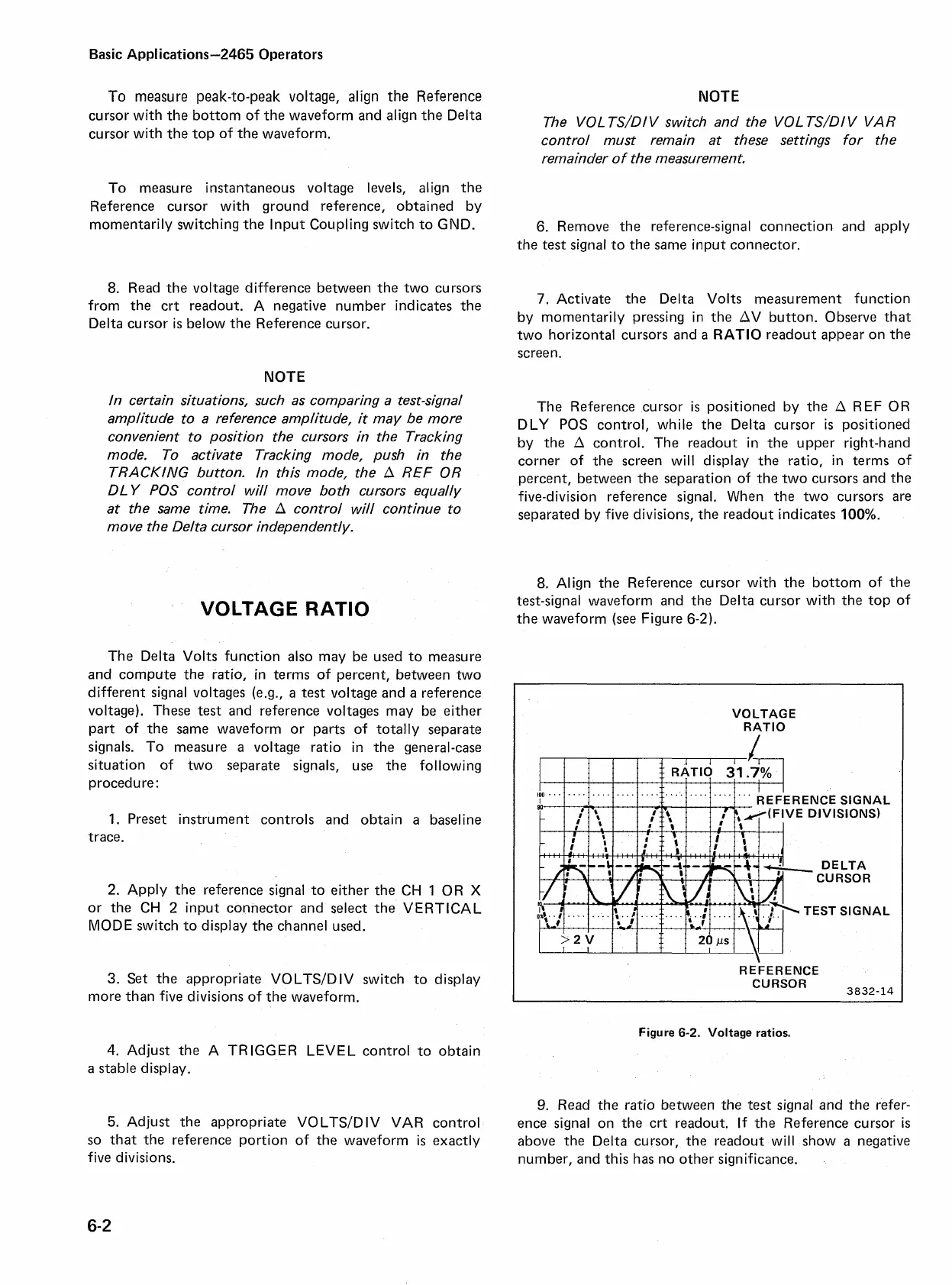
8.
Align the Reference cursor with the bottom of the
test-signal waveform and the Delta cursor with the top of
the waveform (see Figure
6-2).
VOLTAGE
RATIO
ERENCE SIGNAL
VE DIVISIONS)
DELTA
CURSOR
REFERENCE
3832-14
Figure
6-2.
Voltage ratios.
9.
Read the ratio between the
test
signal and the refer-
ence signal on the crt readout. If the Reference cursor is
above the Delta cursor, the readout will show
a
negative
number, and this has no other significance.