Operating Instructions— Type 503
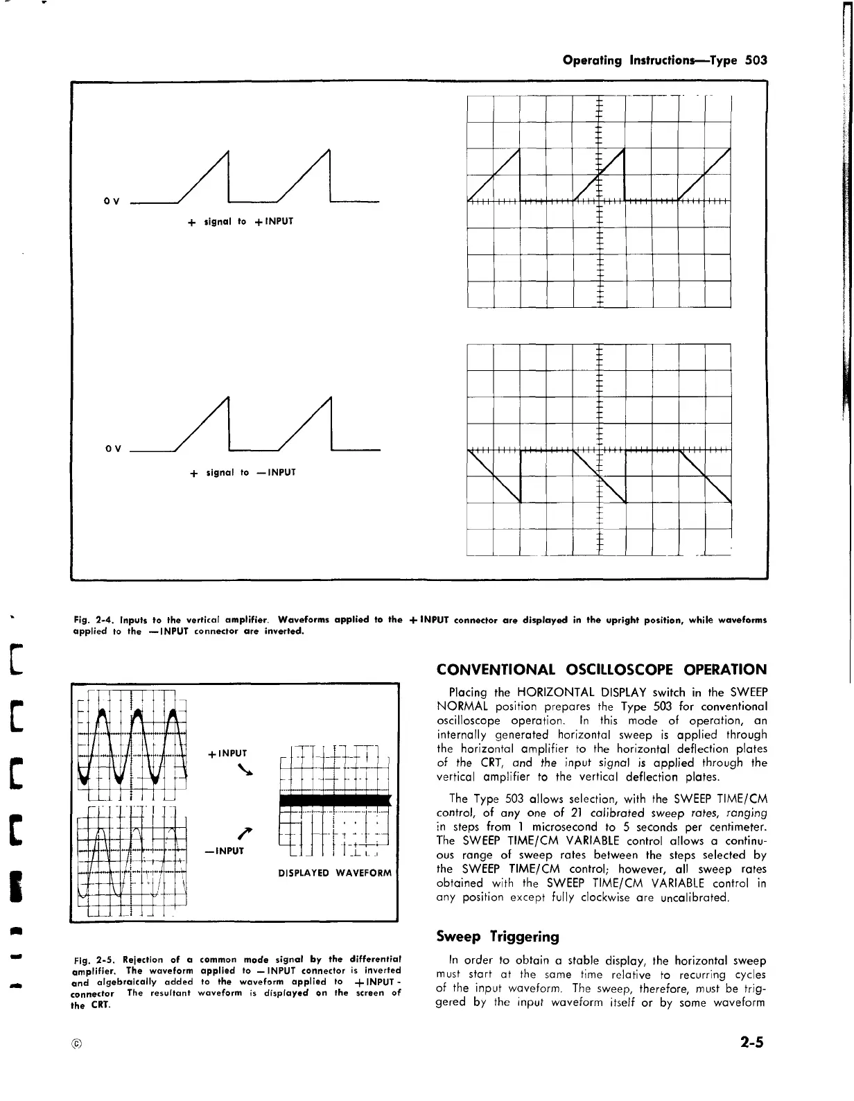
Fig. 2-4. Inputs to the vertical amplifier. Waveforms applied to the + INPUT connector are displayed in the upright position, while waveforms
applied to the — INPUT connector are inverted.
Fig. 2-5. Rejection of a common mode signal by the differential
amplifier. The waveform applied to — INPUT connector is inverted
and algebraically added to the waveform applied to INPUT -
connector The resultant waveform is displayed on the screen of
the CRT.
CONVENTIONAL OSCILLOSCOPE OPERATION
Placing the HORIZONTAL DISPLAY switch in the SWEEP
NORMAL position prepares the Type 503 for conventional
oscilloscope operation. In this mode of operation, an
internally generated horizontal sweep is applied through
the horizontal amplifier to the horizontal deflection plates
of the CRT, and the input signal is applied through the
vertical amplifier to the vertical deflection plates.
The Type 503 allows selection, with the SWEEP TIME/CM
control, of any one of 21 calibrated sweep rates, ranging
in steps from 1 microsecond to 5 seconds per centimeter.
The SWEEP TIME/CM VARIABLE control allows a continu
ous range of sweep rates between the steps selected by
the SWEEP TIME/CM control; however, all sweep rates
obtained with the SWEEP TIME/CM VARIABLE control in
any position except fully clockwise are uncalibrated.
Sweep Triggering
In order to obtain a stable display, the horizontal sweep
must start at the same time relative to recurring cycles
of the input waveform. The sweep, therefore, must be trig
gered by the input waveform itself or by some waveform
©
2-5