Calibration— Type 503
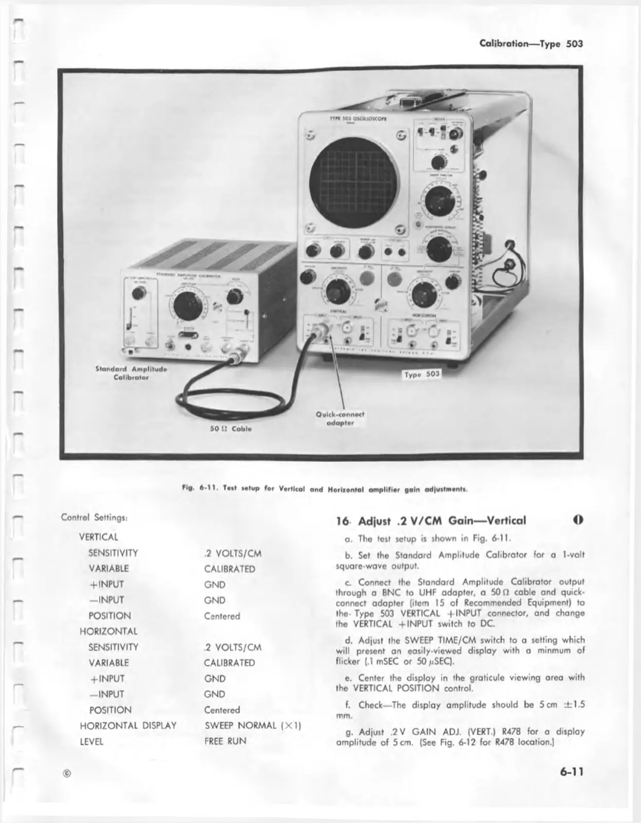
Fig. 6-11. T»if »«tup for Vortical and H oriionta l am plifier gain adjuttm ontt.
Control Settings:
VERTICAL
SENSITIVITY
.2 VOLTS/CM
VARIABLE
CALIBRATED
+ INPUT
GND
-INPU T
GND
POSITION
Centered
HORIZONTAL
SENSITIVITY
.2 VOLTS/CM
VARIABLE
CALIBRATED
+ INPUT
GND
-IN PU T
GND
POSITION
Centered
HORIZONTAL DISPLAY
SWEEP NORMAL (XI)
LEVEL
FREE RUN
16 Adjust .2 V/CM Gain— Vertical O
a. Tho test setup is shown in Fig. 6-11.
b. Set the Standard Amplitude Calibrator for a 1-volt
square-wove output.
c. Connect the Standard Amplitude Calibrator output
through a BNC to UHF adapter, a 50 D cable and quick-
connect adopter (item 15 of Recommended Equipment) to
the- Type 503 VERTICAL -f INPUT connector, and change
the VERTICAL + INPUT switch to DC.
d. Adjust the SWEEP TIME/CM switch to a setting which
will present an easily-viewed display with a minmum of
flicker (.1 mSEC or 50 /(SEC).
e. Center the display in the graticule viewing area with
the VERTICAL POSITION control.
f. Check—The display amplitude should be 5 cm ± 1.5
mm.
g. Adjust ,2 V GAIN ADJ. (VERT.) R478 for a display
amplitude of 5 cm. (See Fig. 6-12 for R478 location.)
©
6-11