Calibration— Type 503
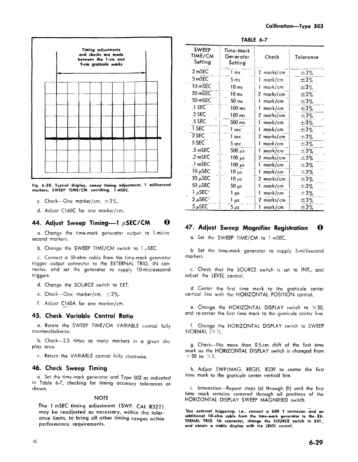
Timing adjustments
and checks are made
between the 1-im and
9-cm graticule marks
Fig. 6-30. Typical display, sweep timing adjustment; 1 millisecond
markers; SWEEP TIME/CM switching, 1 mSEC.
c. Check— One marker/cm, ± 3% .
d. Adjust C160C for one marker/cm.
44. Adjust Sweep Timing— 1 ^SEC/CM O
a. Change the time-mark generator output to 1-micro
second markers.
b. Change the SWEEP TIME/CM switch to 1 /iSEC.
c. Connect a 50-ohm cable from the time-mark generator
trigger output connector to the EXTERNAL TRIG. IN con
nector, and set the generator to supply 10-microsecond
triggers.
d. Change the SOURCE switch to EXT.
e. Check— One marker/cm, ± 3 % .
f. Adjust C160A for one marker/cm.
45. Check Variable Control Ratio
a. Rotate the SWEEP TIME/CM VARIABLE control fully
counterclockwise.
b. Check—2.5 times as many markers in a given dis
play area.
c. Return the VARIABLE control fully clockwise.
TABLE 6-7
SWEEP
Time-Mark
TIME/CM
Generator
Check
Tolerance
Setting
Setting
2 mSEC
1 ms
2 marks/cm
± 3%
5 mSEC
5 ms
1 mark/cm
±3%
10 mSEC
10 ms 1 mark/cm
± 3 %
20 mSEC
10 ms
2 marks/cm
±3%
50 mSEC
50 ms
1 mark/cm
± 3 %
.1 SEC
100 ms 1 mark/cm
± 3%
.2 SEC
100 ms 2 marks/cm
± 3%
.5 SEC
500 ms 1 mark/cm
± 3 %
1 SEC
1 sec
1 mark/cm
± 3 %
2 SEC
1 sec
2 marks/cm
± 3 %
5 SEC
5 sec
1 mark/cm ± 3 %
.5 mSEC
500 /rs 1 mark/cm
± 3%
.2 mSEC
100 Ms 2 marks/cm
± 3 %
.1 mSEC
100/is 1 mark/cm
± 3 %
10 fxSEC
1 0 / is
1 mark/cm ± 3 %
20 ju,SEC
1 0 /is
2 marks/cm
± 3 %
50 /i.SEC
50 fts
1 mark/cm
± 3%
1 ix SEC:‘
1 /IS
1 mark/cm
± 3 %
2 /iSEC1
1
/IS
2 marks/cm
± 3%
5/cSEC
5 as 1 mark/cm ± 3 %
47. Adjust Sweep Magnifier Registration O
a. Set the SWEEP TIME/CM to 1 mSEC.
b. Set the time-mark generator to supply 5-millisecond
markers.
c. Check that the SOURCE switch is set to I NT., and
adjust the LEVEL control.
d. Center the first time mark to the graticule center
vertical line with the HORIZONTAL POSITION control.
e. Change the HORIZONTAL DISPLAY switch to X50,
and re-center the first time mark to the graticule center line.
f. Change the HORIZONTAL DISPLAY switch to SWEEP
NORMAL (X I).
g. Check— No more than 0.5 cm shift of the first time
mark as the HORIZONTAL DISPLAY switch is changed from
X 50 to X I.
46. Check Sweep Timing
a. Set the time-mark generator and Type 503 as indicated
in Table 6-7, checking for timing accuracy tolerances as
shown.
NOTE
The 1 mSEC timing adjustment (SWP. CAL R322)
may be readjusted as necessary, within the toler
ance limits, to bring all other timing ranges within
performance requirements.
h. Adjust SWP/MAG. REGIS. R339 to center the first
time mark to the graticule center vertical line.
i. Interaction— Repeat steps (e) through (h) until the first
time mark remains centered through all positions of the
HORIZONTAL DISPLAY SWEEP MAGNIFIED switch.
‘Use external triggering; i.e., connect a UHF T connector and an
additional 50-ohm cable from the time-mark generator to the EX
TERNAL TRIG. IN connector, change the SOURCE switch to EXT,,
and obtain a stable display with the LEVEL control.
tc)
6-29