Calibration— Type 503
q. Check— Trace separation (measured on the graticule
center vertical line) at the widest part of the ellipse not more
than 1 mm (1 °).
r. Adjust C368 for minimum trace separation; adjust as
necessary for minimum trace separation at 350 kHz and
450 kHz.
NOTE
A compromise adjustment of C368 may be neces
sary to achieve minimum trace separation at both
350 kHz and 450 kHz.
s. Move both signal cables to the HORIZONTAL and
VERTICAL + INPUT connectors, and change both + INPUT
switches to DC, and both —INPUT switches to GND.
t. Check—Trace separation not more than 1 mm.
u. Adjust C468 for minimum trace separation; adjust as
necessary for minimum trace separation at 350 kHz and
450 kHz.
NOTE
Slight re-adjustment of C419 may be required to
obtain minimum trace separation.
v. Change the VERTICAL and HORIZONTAL SENSITIVITY
switches to 1 mV/CM.
w. Adjust the generator output for an X and Y deflection
of 6 cm at 450 kHz, and center the trace.
x. Check— Trace separation not more than 1 mm.
y. Adjust C356 for minimum trace separation; adjust as
necessary for minimum trace separation at 350 kHz and
450 kHz.
z. Change the signal cables to the —INPUT connectors,
set the —INPUT switches to DC, and the + INPUT switches
to GND.
aa. Check—Trace separation not more than 1 mm.
ab. Adjust C456 for minimum trace separation; adjust
as necessary for minimum trace separation at 350 kHz and
450 kHz.
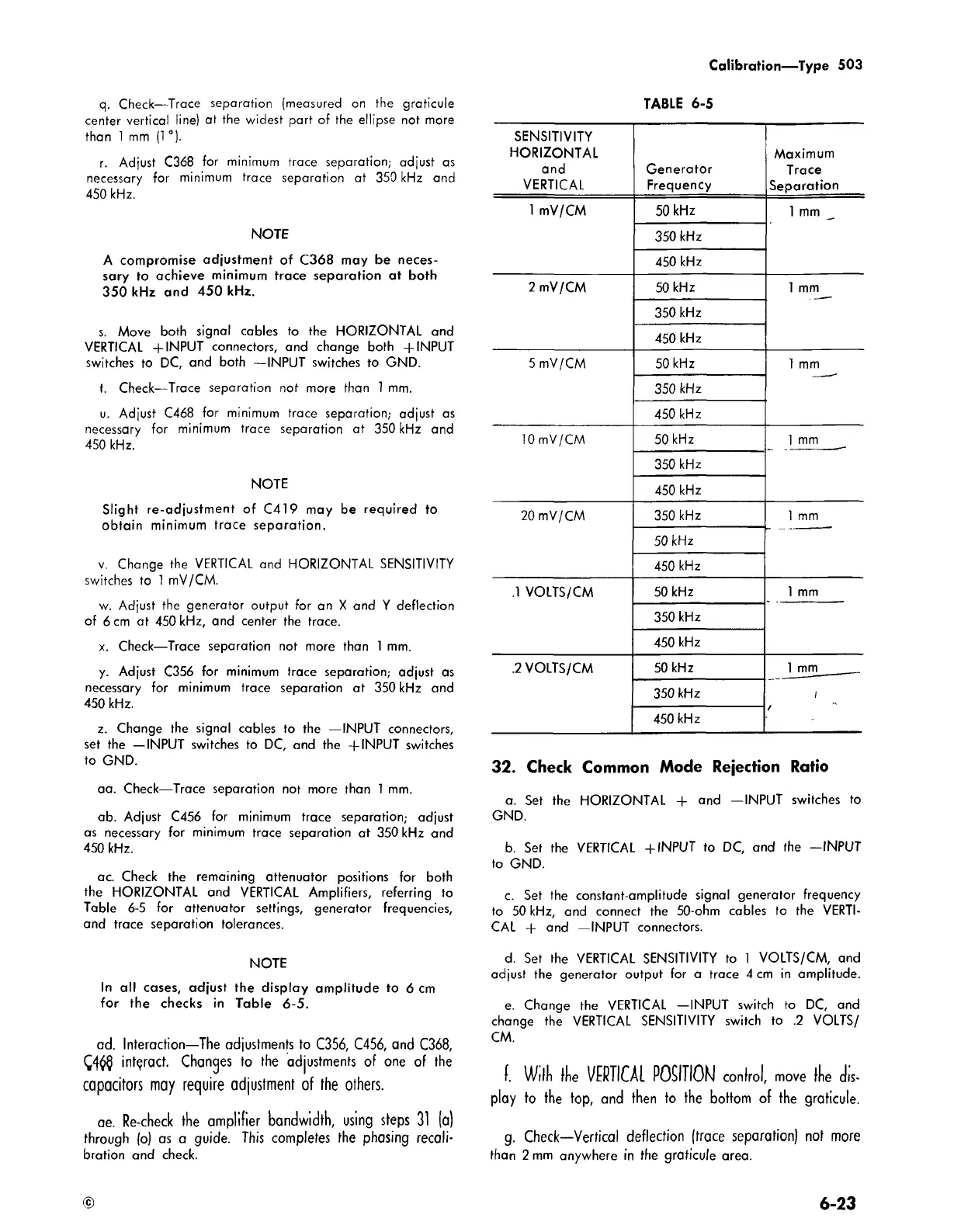
ac. Check the remaining attenuator positions for both
the HORIZONTAL and VERTICAL Amplifiers, referring to
Table 6-5 for attenuator settings, generator frequencies,
and trace separation tolerances.
NOTE
In all cases, adjust the display amplitude to 6 cm
for the checks in Table 6-5.
ad. Interaction—The adjustments to C356, C456, and C368,
interact. Changes to the adjustments of one of the
capacitors m ay require adjustment of the others.
ae. Re-check the amplifier bandwidth, using steps
31
(a)
through (o) as a guide. This completes the phasing recali
bration and check.
TABLE 6-5
SENSITIVITY
HORIZONTAL
and
VERTICAL
Generator
Frequency
Maximum
Trace
Separation
1 mV/CM
50 kHz
1 mm
350 kHz
450 kHz
2 mV/CM 50 kHz
1 mm
350 kHz
450 kHz
5 mV/CM 50 kHz 1 mm
350 kHz
450 kHz
10 mV/CM
50 kHz
1 mm
350 kHz
450 kHz
20 mV/CM 350 kHz
1 mm
50 kHz
450 kHz
.1 VOLTS/CM
50 kHz 1 mm
350 kHz
450 kHz
.2 VOLTS/CM
50 kHz
1 mm
______
/
350 kHz
450 kHz
32. Check Common Mode Rejection Ratio
a. Set the HORIZONTAL + and —INPUT switches to
GND.
b. Set the VERTICAL + INPUT to DC, and the -IN PU T
to GND.
c. Set the constant-amplitude signal generator frequency
to 50 kHz, and connect the 50-ohm cables to the VERTI
CAL + and —INPUT connectors.
d. Set the VERTICAL SENSITIVITY to 1 VOLTS/CM, and
adjust the generator output for a trace 4 cm in amplitude.
e. Change the VERTICAL —INPUT switch to DC, and
change the VERTICAL SENSITIVITY switch to .2 VOLTS/
CM.
f. W illi Hie VERTICAL POSITION control, move fTie dis
play to the top, and then to the bottom of the graticule.
g. Check—Vertical deflection (trace separation) not more
than 2 mm anywhere in the graticule area.
©
6-23