Calibration— Type 503
a. Test setup is shown in Fig. 6-24.
b. Connect a 50 fi termination, a UHF T connector, and
two 50-ohm cables to the output connector of the constant-
amplitude signal generator. If desired, two quick-connect
adapters (item 15 of Recommended Equipment) may be
installed at the Type 503 input ends of the cables, to per
mit easy cable-switching,
NOTE
The two 50-ohm cables should be identical to
assure a symmetrical input to the two amplifiers
for phasing adjustments.
c. Connect the two cables to the VERTICAL and HORI
ZONTAL + INPUT connectors.
d. Adjust the generator output for a 6-cm display at
a frequency of 50 kHz, and center the display exactly with
the VERTICAL and HORIZONTAL POSITION controls.
e. Change the generator frequency to 450 kHz.
f. Check—A vertical trace > 4.2 cm in length.
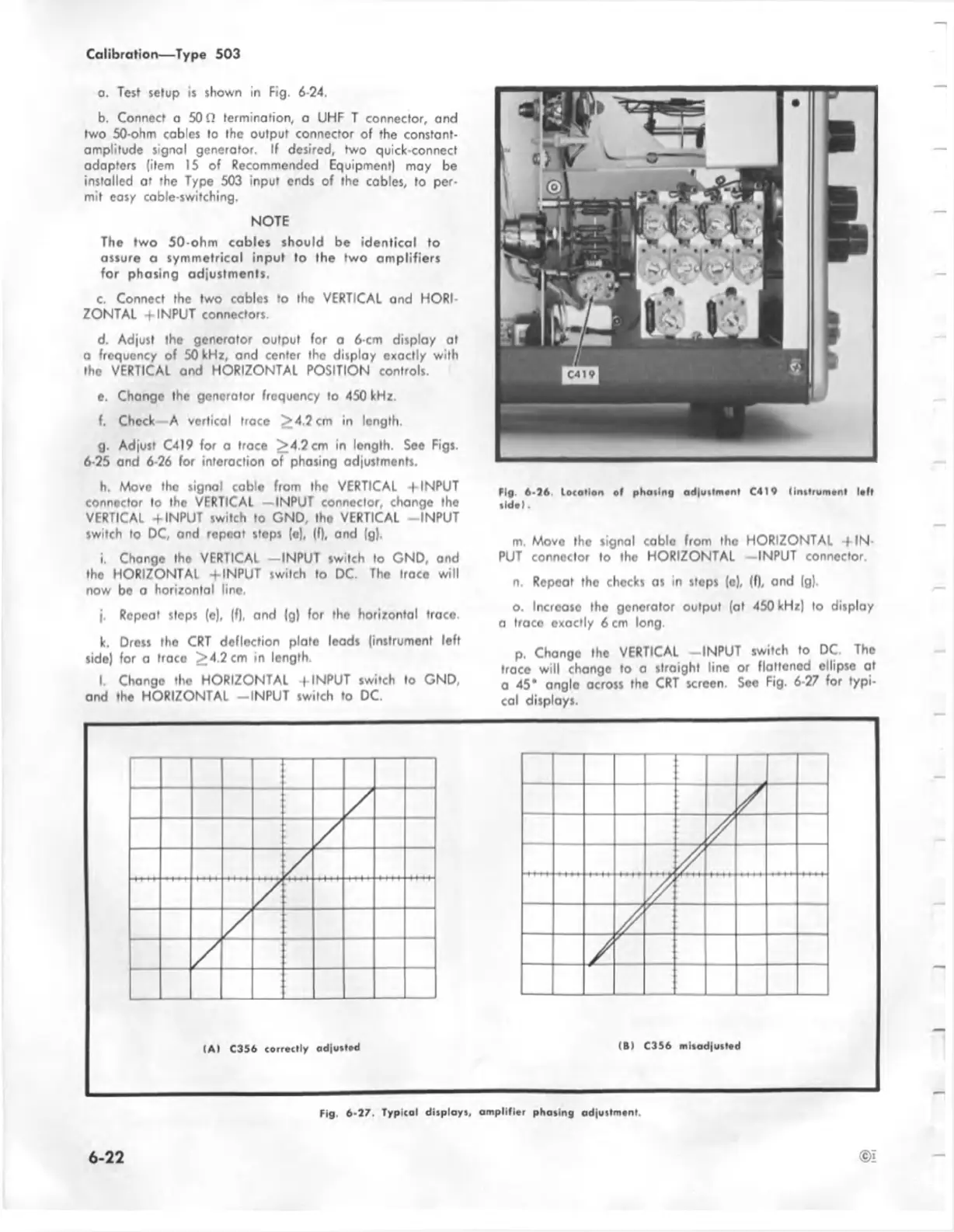
g. Adjust C419 for a trace ^4 .2 cm in length. See Figs.
6-25 and 6-26 for interaction of phasing adjustments.
h. Move the signal cable from the VERTICAL -f INPUT
connector to the VERTICAL —INPUT connector, change the
VERTICAL + INPUT switch to GND, the VERTICAL -INPU T
switch to DC, and repeat steps (e), (f), and (g).
i. Change the VERTICAL —INPUT switch to GND, and
tho HORIZONTAL -fINPUT switch to DC. The trace will
now be o horizontal line.
j. Repeat steps (o), (f), and |g) for tho horizontal trace.
k. Dress the CRT deflection plate leods (instrument left
side) for a trace >4.2 cm in length.
l. Chongo tho HORIZONTAL -fINPUT switch to GND,
and the HORIZONTAL -IN P U T switch to DC.
Fig. 6-26 lecarlon of phasing ad|utlmonl C 4I9 linttrum ont loft
•Id o l.
m. Move the signal cable from the HORIZONTAL -f IN
PUT connector to the HORIZONTAL —INPUT connector.
n. Repeat tho checks as in steps (e), (f), and (g).
o. Increoso tho generator output (at 450 kHz) to display
a trace exactly 6 cm long.
p. Change the VERTICAL -IN PU T switch to DC The
trace will change to a straight line or flattened ellipse at
a 45* angle across the CRT screen. See Fig. 6-27 for typi
cal displays.
6 -2 2
©i
Fig. 6-27. Typical displays, amplifier phasing adjustment.
 Loading...


