Calibration— Type 503
c. Adjust the VERTICAL SENSITIVITY switch and VARI
ABLE control so that the markers fill the vertical graticule
area, and turn the TRIGGER LEVEL fully counterclockwise
to AUTO.
d. Adjust the SWEEP TIME/CM switch and VARIABLE
control for 1 marker/cm.
e. Change the time-mark generator output to 0.1 milli
second. The display should now consist of markers 1 mm
apart filling the graticule area.
f. Check—Maximum tilt of vertical markers not to exceed
I mm right or left of vertical graticule lines.
11. Check Focus
a. Adjust FOCUS control for optimum focus.
b. Check— 1-mm markers should be resolved over entire
graticule area with optimum setting of FOCUS control.
c. Return the VERTICAL and SWEEP TIME/CM VARIABLE
controls to CALIBRATED.
12. Adjust Magnifier Registration O
(Preliminary)
a. Change tho SWEEP TIME/CM ro I mSEC.
b. Change the time mark generator to supply 5-millisec
ond markers.
c. Adjust the VERTICAL SENSITIVITY and VARIABLE con-
trol to display markers 3 cm in amplitude.
d. Change the HORIZONTAL DISPLAY switch to X50.
e. With the HORIZONTAL POSITION control, center tho
middle markers to the graticule center vertical lino.
f. Chango the HORIZONTAL DISPLAY switch to SWEEP
NORMAL (X I).
g. Adjust SWP/MAG REGIS. R339 to re-center the middle
marker to tho graticule center vortical line.
13. Check Horizontal Drift— Preliminary
a. Change the HORIZONTAL DISPLAY switch to X50.
b. Check— Tho magnified display should not drift more
than 4 mm.
c. Change the HORIZONTAL DISPLAY switch to SWEEP
NORMAL (X I), and remove the time-mark generator signal.
d. Return the VERTICAL SENSITIVITY VARIABLE control
to CALIBRATED.
14. Adjust Coarse DC Balance— Vertical O
o. Set the TRIGGER LEVEL control clockwise to FREE
RUN.
b. Change the VERTICAL SENSITIVITY switch to .2 VOLTS/
CM, and the VERTICAL -f INPUT to GND.
c. Center the Vertical POSITION control knob.
— d. Set the DC BAL control to midrange ifound by rotat
ing the knob fully clockwise and counterclockwise; then set
ting to the approximate midrange).
e. Position the trace to the center horizontal line with
tbe Vertical POSITION control.
f. Change the Vertical SENSITIVITY switch to 50mV/CM.
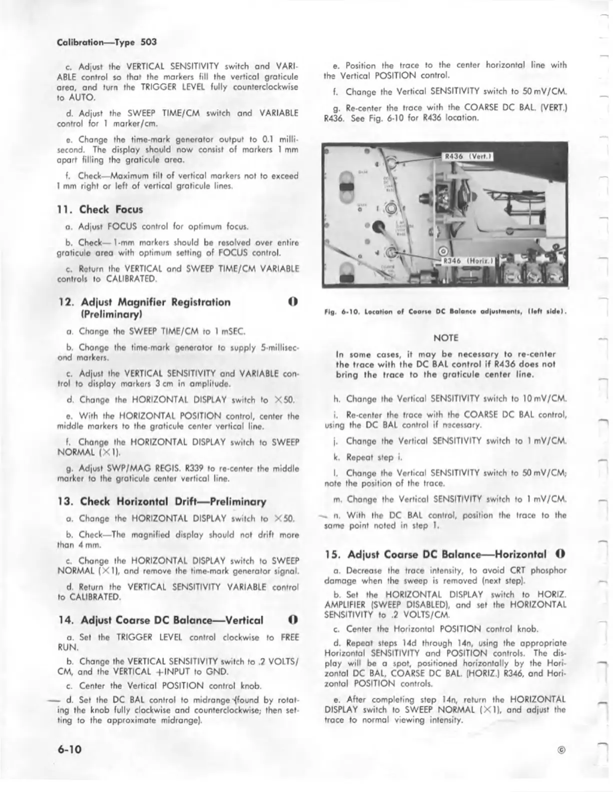
g. Re-center the trace with the COARSE DC BAL. (VERT.)
R436. See Fig. 6-10 for R436 location.
Fig. 6-10. Location of C oart* DC Balanco adjustments, (lo ft tid e ).
NOTE
In some cases, it moy be necessary to re-center
the trace with the DC BAL control if R436 does not
bring the trace to the graticule center line.
h. Change tho Vertical SENSITIVITY switch to lOmV/CM.
i. Ro-center the trace with the COARSE DC BAL control,
using the DC BAL control if necessory.
j. Change the Vertical SENSITIVITY switch to 1 mV/CM.
k. Repeat step i.
l. Change the Vertical SENSITIVITY switch to 50 mV/CM;
note the position of the trace.
m. Chonge the Vertical SENSITIVITY switch to 1 mV/CM.
n. With the DC BAL control, position the trace to tho
same point noted in step 1.
15. Adjust Coarse DC Balance— Horizontal O
a. Decrease the trace intensity, to avoid CRT phosphor
damoge when the sweep is removed (next step).
b. Set the HORIZONTAL DISPLAY switch to HORIZ
AMPLIFIER (SWEEP DISABLED), and set the HORIZONTAL
SENSITIVITY to .2 VOLTS/CM.
c. Center tbe Horizontal POSITION control knob.
d. Repeat steps 14d through 14n, using the appropriate
Horizontal SENSITIVITY and POSITION controls. The dis
play will be a spot, positioned horizontally by the Hori
zontal DC BAL, COARSE DC BAL. (HORIZ.) R346, and Hori-
zontal POSITION controls.
e. After completing step 14n, return the HORIZONTAL
DISPLAY switch to SWEEP NORMAL (X I), and adjust the
trace to normal viewing intensity.
6 -1 0
©