C alibration— Type 503
i. Change the test oscilloscope Time/cm switch to 0.1
milliseconds.
j. Set the autotransformer output to 117 V.
k. Check—No more than 5 mV of 30 kHz ripple.
l. Repeat steps (h) and (k) for the +100 V, and +250 V,
referring to Fig. 6-7 for the location of the test points.
m. Check—30 kHz ripple tolerance as indicated in Table
6-1.
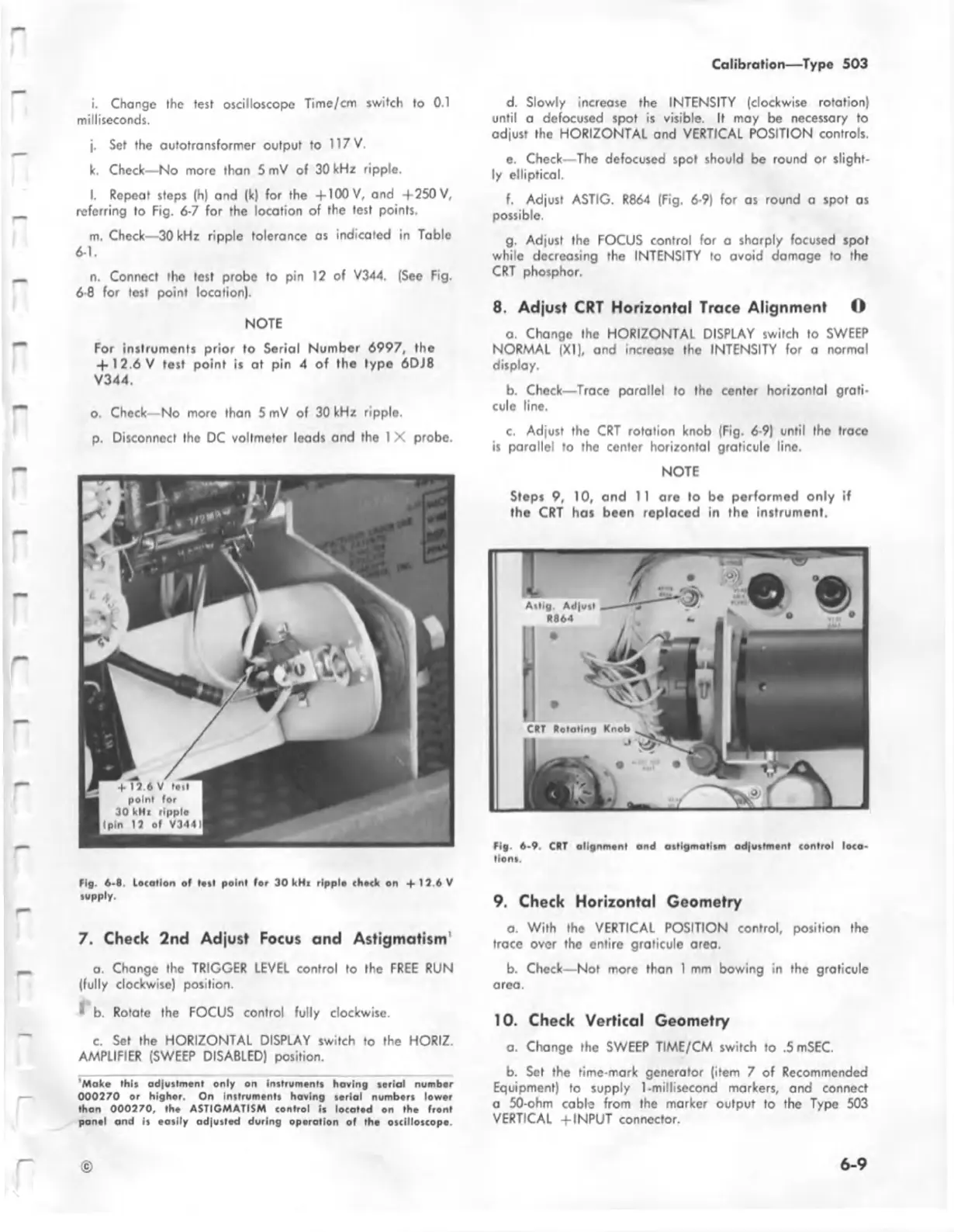
n. Connect the test probe to pin 12 of V344. (See Fig.
6-8 for test point location).
NOTE
For instruments prior to Serial Number 6997, the
+ 12 .6V test point is at pin 4 o f the type 6DJ8
V344.
o. Check— No more than 5 mV of 30 kHz ripple.
p. Disconnect the DC voltmeter leads and the 1 X probe.
fig . 6-8 location of tott point for 30 kHz ripplo chock on «f 12.6V
supply.
7. Check 2nd Adjust Focus and Astigmatism'
a. Change the TRIGGER LEVEL control to the FREE RUN
(fully clockwise) position.
^ b. Rotate the FOCUS control fully clockwise.
c. Set the HORIZONTAL DISPLAY switch to the HORIZ.
AMPLIFIER (SWEEP DISABLED) position.
'Make this adjustment only on instruments having serial number
00 0270 or higher. On instruments having serial numbers lower
than 000270, the ASTIGMATISM control is located on the front
panel and is easily adjusted during operation of the oscilloscope.
d. Slowly increase the INTENSITY (clockwise rotation)
until a dcfocused spot is visible. It may be necessary to
adjust the HORIZONTAL and VERTICAL POSITION controls.
e. Check—The defocused spot should be round or slight
ly elliptical.
f. Adjust ASTIG. R864 (Fig. 6-9) for as round a spot as
possible.
g. Adjust the FOCUS control for a sharply focused spot
while decreasing the INTENSITY to avoid damage to the
CRT phosphor.
8. Adjust CRT Horizontal Trace Alignment O
a. Change the HORIZONTAL DISPLAY switch to SWEEP
NORMAL (XI), and increase the INTENSITY for a normal
display.
b. Check— Trace parallel to the center horizontal grati
cule line.
c. Adjust the CRT rotation knob (Fig. 6-9) until the trace
is parallel to the center horizontal graticule line.
NOTE
Steps 9, 10, and 11 are to be performed only if
the CRT has been replaced in the instrument.
fig . 6-9. CRT allgnm .nl and atllgm alltm adiw ilm .nl <ontrol loco,
lion*.
9. Check Horizontal Geometry
a. With the VERTICAL POSITION control, position the
trace over the entire graticule area.
b. Check— Not more than 1 mm bowing in the graticule
area.
10. Check Vertical Geometry
a. Change the SWEEP TIME/CM switch to .5 mSEC.
b. Set the time-mark generator (item 7 of Recommended
Equipment) to supply 1-millisecond markers, and connect
a 50-ohm cable from the marker output to the Type 503
VERTICAL +INPUT connector.
©
6-9