Performance Check— Type 503
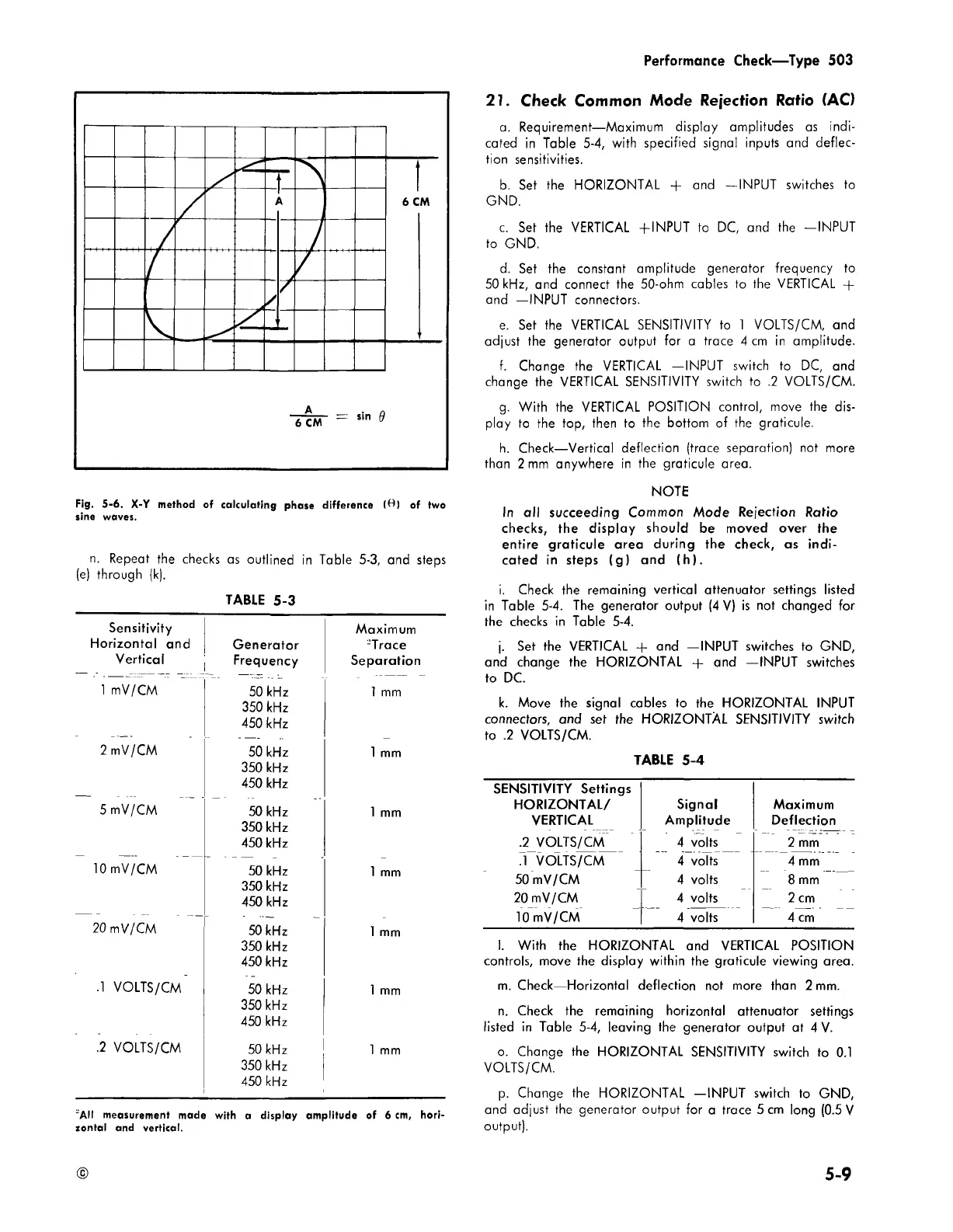
Fig. 5-6. X-Y method of calculating phase difference (ft) of two
sine waves.
n. Repeat the checks as outlined In Table 5-3, and steps
(e) through (k).
TABLE 5-3
Sensitivity
Horizontal and
Vertical
Generator
Frequency
Maximum
2Trace
Separation
1 mV/CM
50 kHz
350 kHz
450 kHz
1 mm
2 mV/CM
50 kHz
350 kHz
450 kHz
1 mm
5 mV/CM
50 kHz
350 kHz
450 kHz
1 mm
10 mV/CM
50 kHz
350 kHz
450 kHz
1 mm
20 mV/CM
50 kHz
350 kHz
450 kHz
1 mm
.1 VOLTS/CM
50 kHz
350 kHz
450 kHz
1 mm
.2 VOLTS/CM
50 kHz
350 kHz
450 kHz
1 mm
~AII measurement made with a display amplitude of 6 cm, hori
zontal and vertical.
21. Check Common Mode Rejection Ratio (AC)
a. Requirement—Maximum display amplitudes as indi
cated in Table 5-4, with specified signal inputs and deflec
tion sensitivities.
b. Set the HORIZONTAL + and —INPUT switches to
GND.
c. Set the VERTICAL +INPUT to DC, and the -INPU T
to GND.
d. Set the constant amplitude generator frequency to
50 kHz, and connect the 50-ohm cables to the VERTICAL +
and —INPUT connectors.
e. Set the VERTICAL SENSITIVITY to 1 VOLTS/CM, and
adjust the generator output for a trace 4 cm in amplitude.
f. Change the VERTICAL —INPUT switch to DC, and
change the VERTICAL SENSITIVITY switch to .2 VOLTS/CM.
g. With the VERTICAL POSITION control, move the dis
play to the top, then to the bottom of the graticule.
h. Check—Vertical deflection (trace separation) not more
than 2 mm anywhere in the graticule area.
NOTE
In all succeeding Common Mode Rejection Ratio
checks, the display should be moved over the
entire graticule area during the check, as indi
cated in steps (g ) and (h ).
i. Check the remaining vertical attenuator settings listed
in Table 5-4. The generator output (4 V) is not changed for
the checks in Table 5-4.
j. Set the VERTICAL -+- and —INPUT switches to GND,
and change the HORIZONTAL + and —INPUT switches
to DC.
k. Move the signal cables to the HORIZONTAL INPUT
connectors, and set the HORIZONTAL SENSITIVITY switch
to .2 VOLTS/CM.
TABLE 5-4
SENSITIVITY Settings
HORIZONTAL/
Signal
Maximum
VERTICAL
Amplitude Deflection
.2 VOLTS/CM 4 volts
2 mm
.1 VOLTS/CM 4 volts
4 mm
50 mV/CM 4 volts
8 mm
20 mV/CM 4 volts 2 cm
10 mV/CM 4 volts 4 cm
I. With the HORIZONTAL and VERTICAL POSITION
controls, move the display within the graticule viewing area.
m. Check—Horizontal deflection not more than 2 mm.
n. Check the remaining horizontal attenuator settings
listed in Table 5-4, leaving the generator output at 4 V.
o. Change the HORIZONTAL SENSITIVITY switch to 0.1
VOLTS/CM.
p. Change the HORIZONTAL —INPUT switch to GND,
and adjust the generator output for a trace 5 cm long (0.5 V
output).
5 -9