Calibration— Type 503
V.
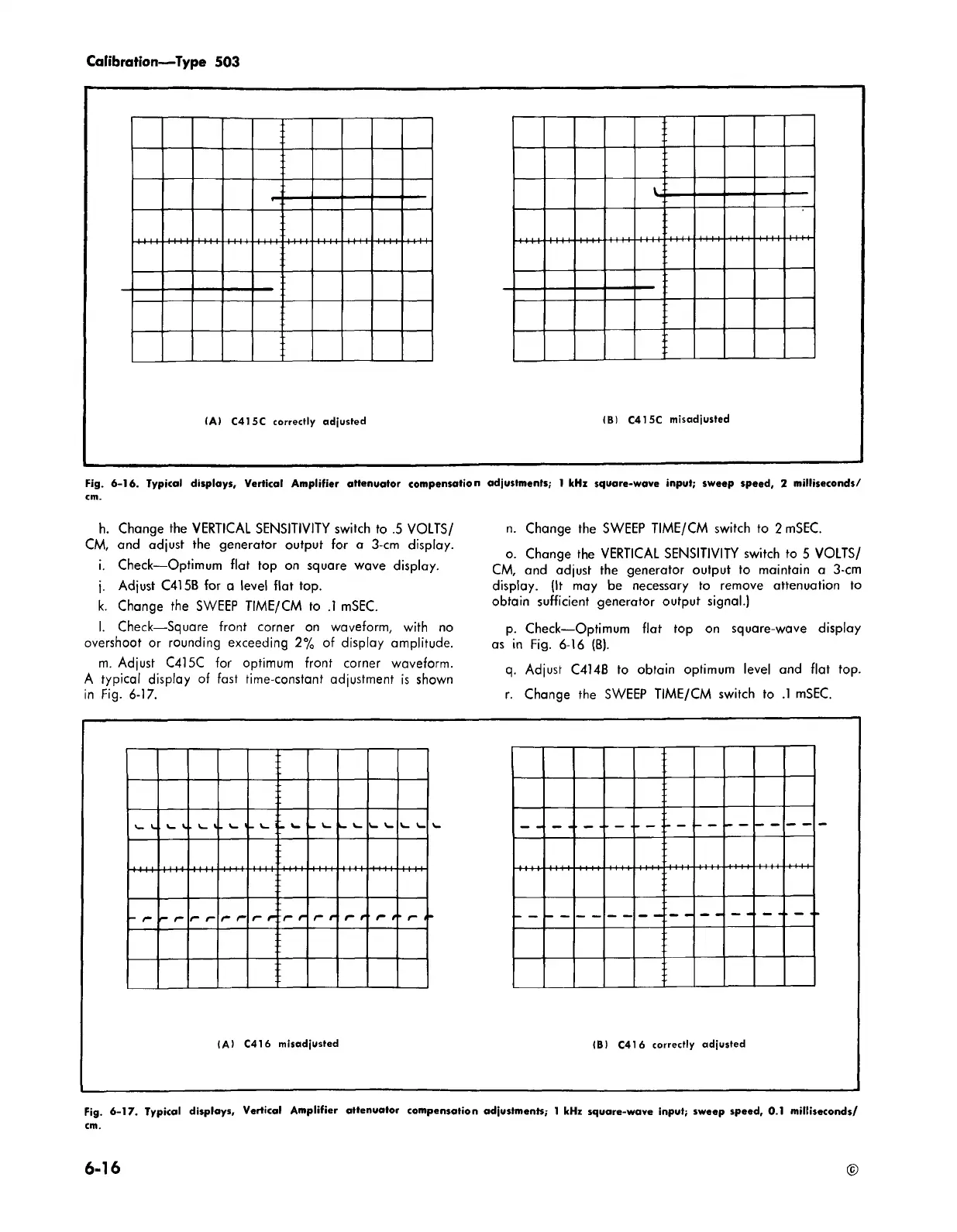
(A ) C415C correctly adjusted
(B) C415C misadjusted
Fig. 6 -16. Typical displays. Vertical A m p lifie r attenu ator compensa tion adjustm ents; 1 kHz square-wave inpu t; sweep speed, 2 m illiseconds/
h. Change the VERTICAL SENSITIVITY switch to .5 VOLTS/
CM, and adjust the generator output for a 3-cm display.
i. Check— Optimum flat top on square wave display.
j. Adjust C415B for a level flat top.
k. Change the SWEEP TIME/CM to .1 mSEC.
l. Check— Square front corner on waveform, with no
overshoot or rounding exceeding 2% of display amplitude.
m. Adjust C415C for optimum front corner waveform.
A typical display of fast time-constant adjustment is shown
in Fig. 6-17.
n. Change the SWEEP TIME/CM switch to 2 mSEC.
o. Change the VERTICAL SENSITIVITY switch to 5 VOLTS/
CM, and adjust the generator output to maintain a 3-cm
display. (It may be necessary to remove attenuation to
obtain sufficient generator output signal.)
p. Check— Optimum flat top on square-wave display
as in Fig. 6-16 (B).
q. Adjust C414B to obtain optimum level and flat top.
r. Change the SWEEP TIME/CM switch to .1 mSEC.
v_ V.
V_ V. V_ V
. v-. <
- V_ !
• w
-
f-
— /“
e~
r r
\n r n r
r
f
r
t
• /“
f
(A) C416 misadjusted
(B) C416 correctly adjusted
Fig. 6 -17. Typical displays. Vertical A m plifie r atte nua tor compensation adjustm ents; 1 kHz square-wave inpu t; sweep speed, 0.1 m illiseconds/
cm.
6-16