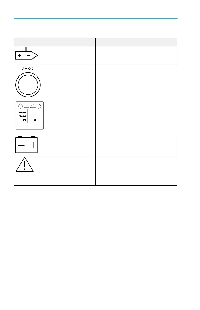
Table 1: A622 controls and indicators
Control/Indicator Description
Current flow symbol. The arrow shows the
polarity convention of the probefor measuring
current flowing from positive to negative.
Zero adjustment. Rotate to adjust the probe
output to zero when there is no current present.
It can also be used to offset a DC signal
component. Zeroing is not needed for AC
measurements unless your instrument cannot
isolate a DC component (if present).
OFF/Range switch. Slide the switch from OFF
to either the 10 mV/A or 100 mV/A range. When
either range is selected, the probe is turned on,
and the green battery indicator lights. If the
indicator does not light, see Battery Notes on
page 7.
Battery indicator. The green battery indicator
lights when the probe is turned on. For more
information, see Battery Notes on page 7.
Overload indicator. The red overload indicator
lights if the measured signal is greater that the
selected range capacity. Switch the probe to
10 mV/A if possible, or remove the probe from
the circuit.
Getting started
2 A622 Instructions