■
Press the Vertical button of the channel just confirmed to remove the
channel from the display.
■
Press the front-panel Vertical button that corresponds to the channel
you are to confirm.
■
< 4 GHz models: Touch Vertical, select Vertical Setup, and then
touch Termination 50 Ω.
■
Set the generator output to 0 V.
■
Move the test hookup to the channel you selected.
b. Turn on the measurement Mean for the channel:
■
From the button bar, touch Measure and select the Ampl tab, More,
and then touch Mean to measure the mean of the current channel.
■
Press the X (Close) button.
NOTE. When setting the Fluke generator to output >5 V with the
instrument termination set to 50 Ω, use the following procedure: Press
the Aux button Press the fourth soft key down (Selects the pulse with an
exclamation point) Set the amplitude to 5.3 or 5.5 V Press the ->| key to
select the pulse energy Set the energy to 50J, and press the Output On
key Press the Trig Pulse soft key to trigger the pulse (this will generate a
pulse with 25 seconds duration). Use the normal DC output for generator
settings ≤5 V at termination setting 50 Ω and for any voltages at a
termination setting of 1 MΩ.
NOTE. If any of the voltages supplied by your generator are not
calibrated, verify those generator voltages using a digital multimeter,
item 27.
c. Set the vertical scale: Set the vertical Scale to one of the settings listed in
the following table that is not yet checked, starting with the first setting
listed.
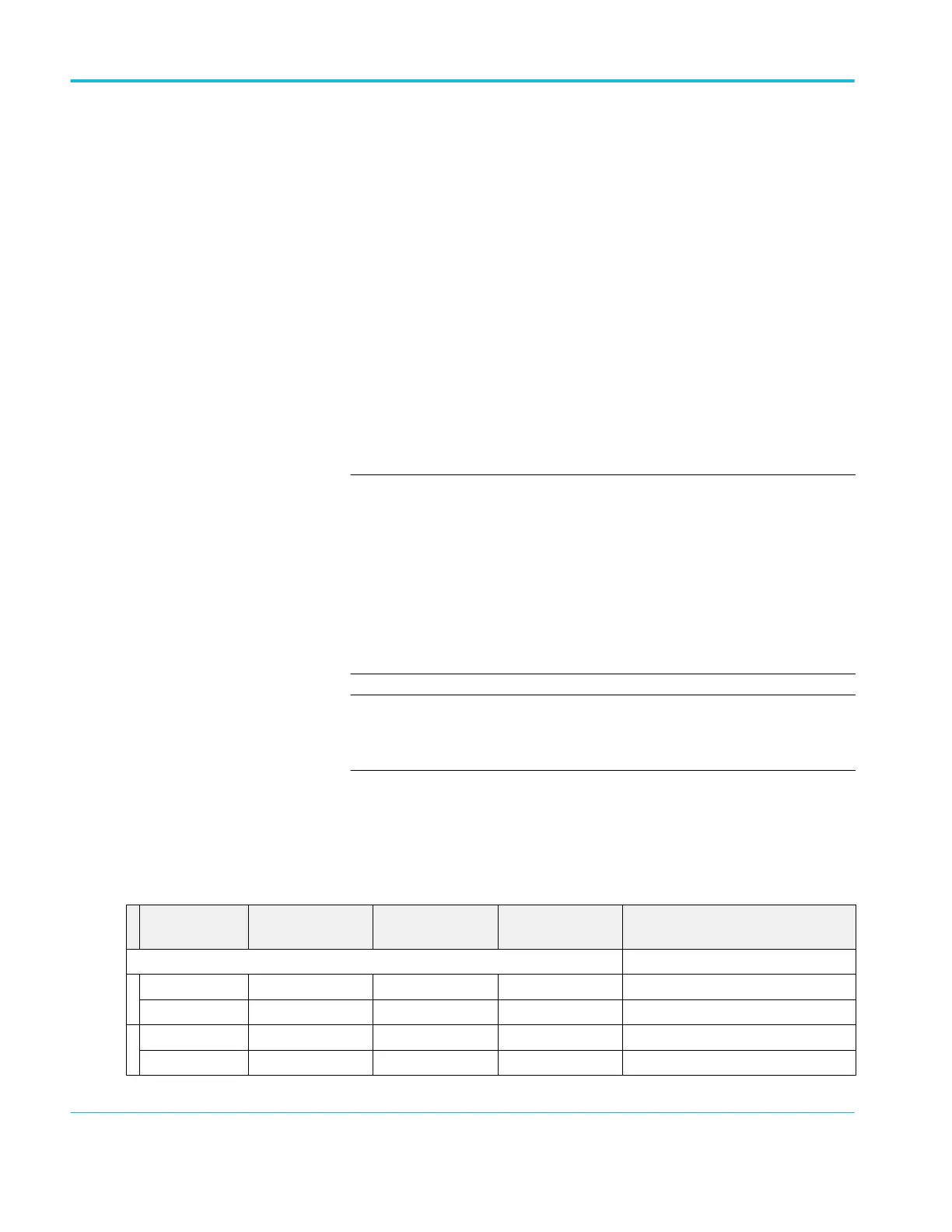
Table 7: DC voltage measurement accuracy
Scale setting Position setting
(Divs)
Offset setting
4
Generator setting Accuracy limits
≥ 4 GHz, ≤20 GHz models
10 mV -5 +0.45 V +530 mV +524.75 mV to +535.25 mV
+5 -0.45 V -530 mV -535.25 mV to -524.75 mV
20 mV -5 +0.4 V +560 mV +552.75 mV to +567.25 mV
+5 -0.4 V -560 mV -567.25 mV to -552.75 mV
4
Set as precisely as the instrument's offset resolution permits.
Performance verification (MSO/DPO70000C, MSO/DPO70000DX, and DPO7000C series)
184 MSO70000C/DX, DPO70000C/DX, DPO7000C, MSO5000/B, DPO5000/B Series
 Loading...

