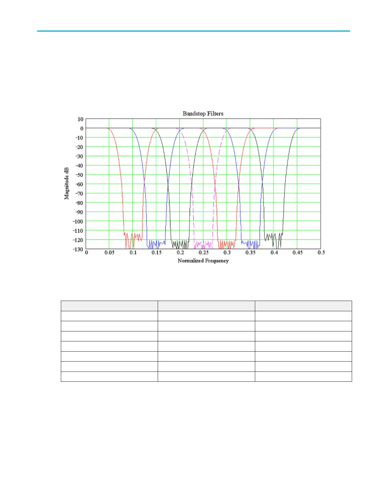
Band stop filters. Each filter has a bandwidth of 0.1 times the sample rate. They will operate at any sample rate. The available
center frequencies are 0.10, 0.15, 0.20, 0.25, 0.30, 0.35, and 0.40. Stop band attenuation is approximately – 110 dB, however,
the noise floor of the oscilloscope will not allow for that depth.
With an FFT and long record length, and averaging turned on, one can approach noise floors in the – 110 dBm range on an 8-bit
oscilloscope. However, the oscilloscope will have some spurious signals above that floor. This is possible because the FFT is an
average calculation internally and the averaging function increases the vertical bits of resolution.
Figure 27: Frequency response of the available band stop filters
The following table lists the available normalized band stop filters:
File name Normalized bandwidth Normalized center frequency
bandstop_0.1bw_0.10center.flt 0.1 0.10
bandstop_0.1bw_0.15center.flt 0.1 0.15
bandstop_0.1bw_0.20center.flt 0.1 0.20
bandstop_0.1bw_0.25center.flt 0.1 0.25
bandstop_0.1bw_0.30center.flt 0.1 0.30
bandstop_0.1bw_0.35center.flt 0.1 0.35
bandstop_0.1bw_0.40center.flt 0.1 0.40
Oscilloscope reference
DPO70000SX, MSO/DPO70000DX, MSO/DPO70000C, DPO7000C, and MSO/DPO5000B Series 789
 Loading...

