Module Removal (DPO7000 Series)
Module Remova
l (DPO7000 Series)
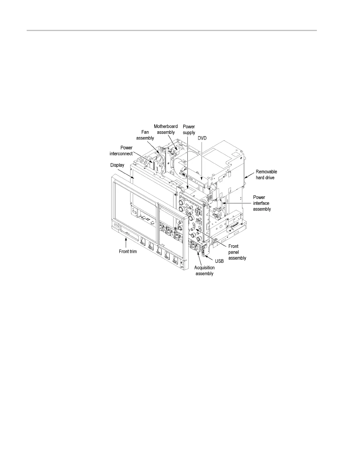
Toremoveamo
dule, refer to the m odule locator. (See Figure 4-1.)
You can also refer to the exploded view diagrams.(See page 5-2, Using the
Replaceabl
ePartsList.)
To access t he modules, refer to the module removal table. (See Table 4-4 on
page 4-9.)
Figure 4-1: DPO7000 Series module locations
4–8 MSO70000/C, DSA70000B/C, DPO70000B/C, DPO7000, MSO5000, DPO5000 Series

 Loading...


