8: Rechargeable battery measurements Model 2450 SourceMeter® Instrument
8-4 2450-900-01 Rev. E / August 2019
Device connections
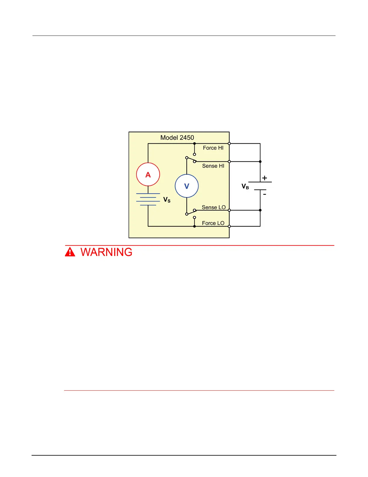
To set up the test, connect the 2450 to the battery as shown in the following figure. Make a 4-wire
(remote sense) connection from the instrument terminals to the battery to eliminate the effects of the
lead resistance. This allows you to measure the battery voltage as closely as possible to the terminals
of the instrument.
Figure 42: Schematic for the battery charge and discharge cycle test
To prevent electric shock, test connections must be configured such that the user cannot
come in contact with conductors or any device under test (DUT) that is in contact with the
conductors. It is good practice to disconnect power before connecting DUTs. Safe installation
requires proper shields, barriers, and grounding to prevent contact with conductors.
There is no internal connection between protective earth (safety ground) and the LO
terminals of the 2450. Therefore, hazardous voltages (more than 30 V
RMS
) can appear on LO
terminals. This can occur when the instrument is operating in any mode. To prevent
hazardous voltage from appearing on the LO terminals, connect the LO terminal to protective
earth (safety ground) if your application allows it. You can connect the LO terminal to the
chassis ground terminal on the front panel or the chassis ground screw terminal on the rear
panel. Note that the front-panel terminals are isolated from the rear-panel terminals.
Therefore, if you are using the front-panel terminals, ground to the front-panel LO terminal. If
using the rear-panel terminals, ground to the rear panel LO terminal. Failure to follow these
guidelines can result in injury, death, or instrument damage.
You can make test connections to the 2450 from the rear or front panel of the instrument.
Connect the FORCE HI and SENSE HI output terminals of the 2450 to the positive (+) terminal of the
battery. Connect the SENSE LO and FORCE LO outputs to the negative (−) terminal of the battery.